SECTION 6 – TEST AND PLACE IN SERVICE
PAGE 6-16 REV. 0 2014-APR-30
CHECKFIRE 110
Detection and Actuation System
TABLE 6-7: PLACING CHECKFIRE 110 CONTROL MODULE IN SERVICE
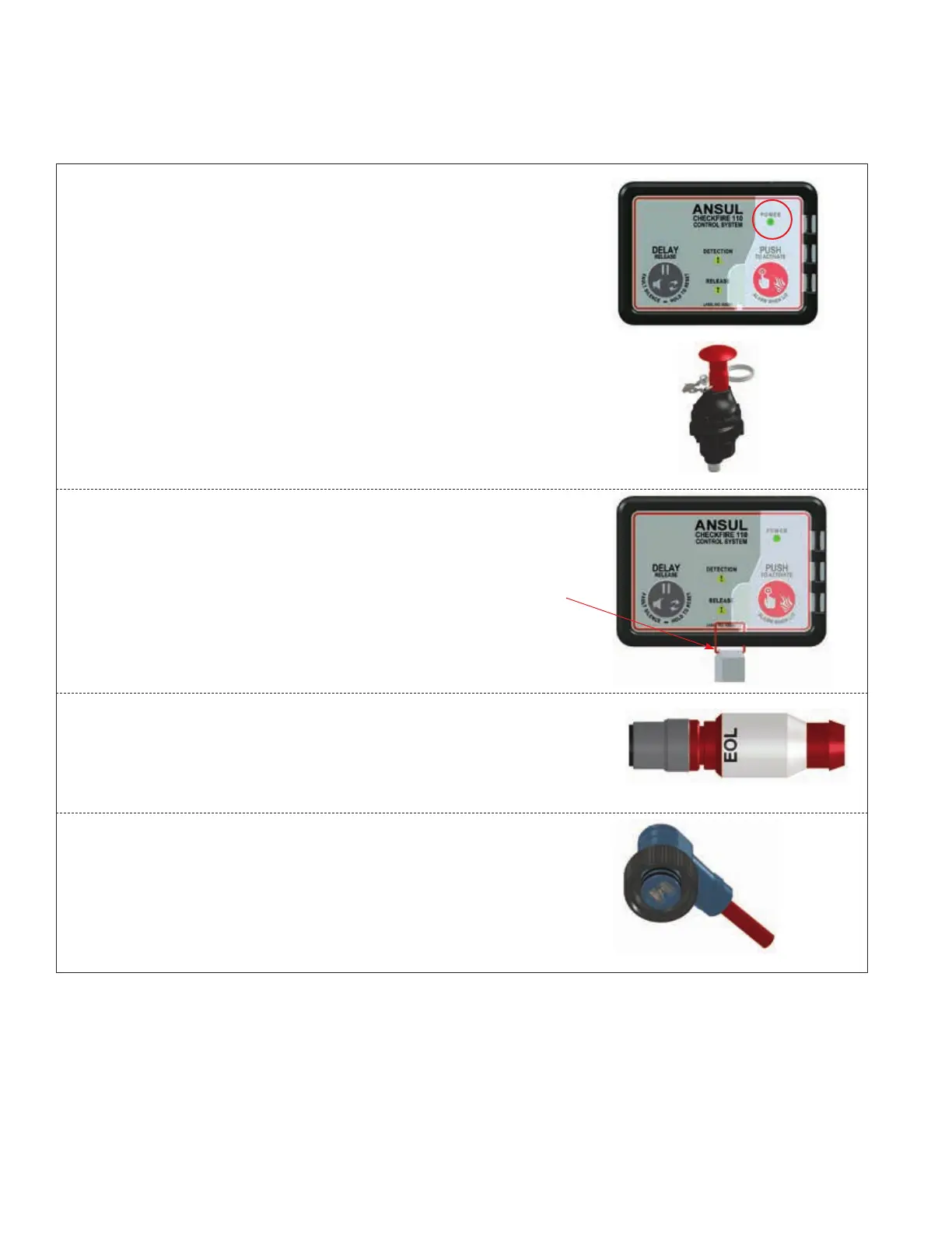
1. Reconnect external power circuit. The Power LED returns
to GREEN steady-on. (At completion of testing return all
devices to normal status.)
2. Confirm all EMAs are in the up / ring-pinned positions
and properly re-sealed with a visual seal.
3. Close guard door for “PUSH To Activate / Alarm When
Lit” button and install visual seal.
4. Replace DCT with Detection EOL Device in the detection
circuit. Detection fault indication starts and then clears.
5. Remove RCT and/or Release Circuit Test Plug from
Release Circuit Drop Cable. Note: Release fault indica-
tion starts and remains in fault until installation of PAD(s).
Continues Next Page
009239
REMOVE RCT AND
RELEASE CIRCUIT
TEST PLUG
009153
ALL EMAs IN UP/PINNED
POSITION AND SEALED
009180
RECONNECT EXTERNAL
POWER, LED IS GREEN
STEADY-ON
009161
REPLACE DCT WITH EOL
DEVICE IN DETECTION
CIRCUIT
009151
SEAL GUARD
DOOR
PROTECTING
RED BUTTON