Legacy AXS API
Slider (Boost and Cut): Sets the amount of boost or cut for the selected band
+12dB of boost and -12dB of cut
0dB detent
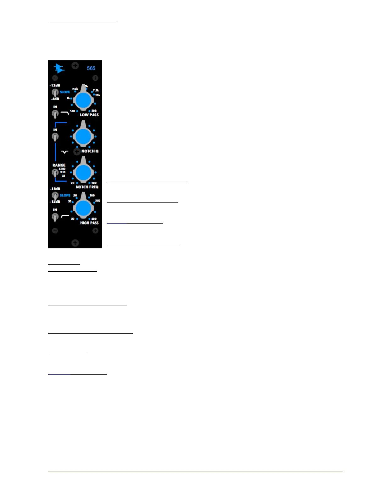
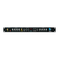
565 Filter Bank
Features
• Sweepable low-pass filter (500Hz to 20kHz, -6 or -12dB/8va slope)
• Sweepable high-pass filter (20Hz to 400Hz, -12 or -18dB/8va slope)
• Variable notch filter:
o Adjustable Q
o Fully sweepable between 20Hz and 20kHz
• Individual bypass switches for each filter section
• Transformer balanced output to +28dBu
• Traditional API fully discrete circuit design
• Uses API 2520 and 2510 Op-Amps as well as the same discrete
transistor buffers used in the famous 550 series equalizers
The 565 Filter Bank module has circuits that are true to the musical filters of the
famed 215 module found in large format API consoles.
The controls for the 565 Filter Bank function as follows:
IN (low-pass in/out switch): Activates the low-pass filter when engaged
Hard bypass when not engaged
LOW PASS (frequency): Sets the frequency of the low-pass filter
• Sweepable from 500Hz to 20kHz
SLOPE (Low-pass): Sets the slope of the low-pass filter
• -6dB/8va or -12dB/8va
IN (Notch in/out switch): Activates the notch filter when engaged.
Hard bypass when not engaged
NOTCH Q: Sets the Q (quality factor) of the notch filter
NOTCH RANGE: Multiplies the Notch FREQ by the following factors:
• x1
• x10
• x100
NOTCH FREQ (frequency): Sets the frequency of the notch filter.
• Sweepable from 20Hz to 20kHz
Notch frequency determined by selected frequency and NOTCH RANGE factor
IN (High-pass in/out switch): Activates the high-pass filter when engaged.
Hard bypass when not engaged
HIGH PASS: Sets the frequency of the high-pass filter.
• Sweepable 20Hz to 600Hz
SLOPE (High-pass): Sets the slope of the high-pass filter.
• -12dB/8va or -18dB/8va
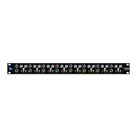
Channel Signal Processing Patch Points
The standard configuration provides a complete set of patch points for the lower 200 slot. There are
no direct 500 Series EQ slot patch points.
Depending on console configuration, there will be signal processing patch points for 32, 48, 64, or 80
channels in the bay. In the interest of space, patch points for only 8 channels are shown below.