Legacy AXS API
Stereo Return Signal Flow
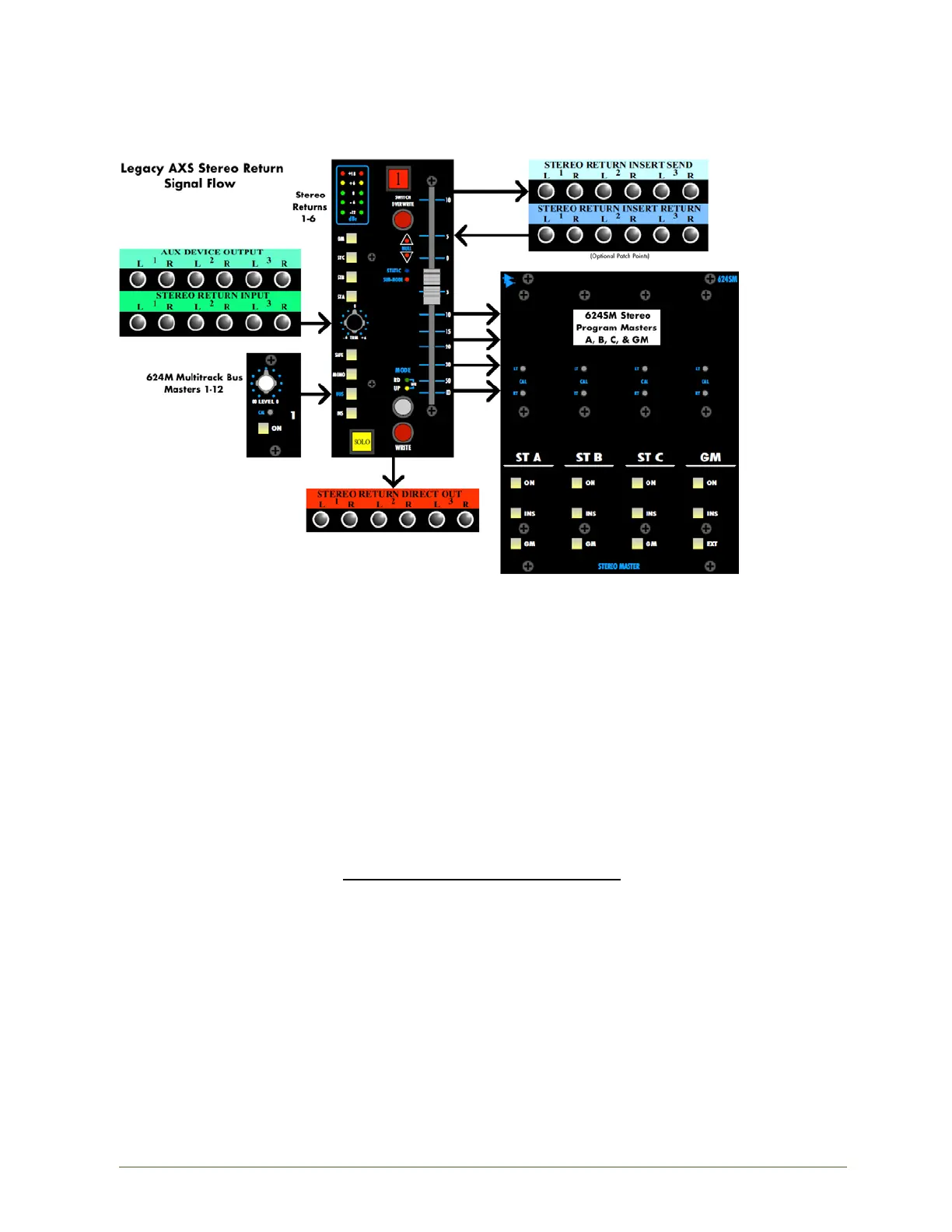
The diagram below shows the basic Stereo Return signal flow from input to the stereo Program
Masters/Grand Master and Direct Output. In interest of space, patch points for only 3 of the 6 Stereo
Returns are shown.
The Stereo Returns have two input options:
• Line-Level: STEREO RETURN INPUT patch points
• Multitrack Bus: Output of the associated Multitrack Bus Master in pairs
The default line inputs to the Stereo Returns are the STEREO RETURN INPUT patch points in the System
patch bay. These patch points are fed from the AUX DEVICE OUTPUT patch points via half-normal.
Outputs of external devices can be connected to the AUX DEVICE OUTPUT patch points via a multi-pin
connector on the rear of the System patch bay. This will allow a normalled regular connection through
the patch bay.
If desired, the output of the associated pair Multitrack Bus Masters can be routed to the Stereo Return
input by engaging the BUS button. This will replace the patch bay input to the return with the bus
output. Only the first 12 Multitrack Buses can be directly routed to the Stereo Returns. The associated
Multitrack Buses are as follows:
Multitrack Buses Stereo Return
1-2 = 1
3-4 = 2
5-6 = 3
7-8 = 4
9-10 = 5
11-12 = 6
The Left and Right inputs to the Stereo Returns can be summed to mono by engaging the MONO
button. This mono summing happens pre-Insert Send.