Table of Contents
About this Manual ............................................................................. 6
Introduction ..................................................................................... 7
Features ................................................................................................. 7
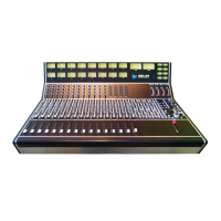
Configuration Options............................................................................. 8
Channel Features .................................................................................... 8
Central Facilities ..................................................................................... 8
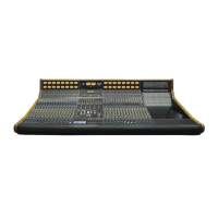
Console Configuration ...................................................................... 9
Mainframe and Channel Slots ................................................................. 9
Channel Bucket ....................................................................................... 9
Upper 200 Slot .................................................................................... 9
Lower 200 Slot .................................................................................. 10
624 Bus Assignment Module Slot ......................................................... 10
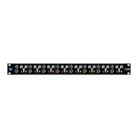
500 Series Equalizer Slot .................................................................... 10
968 Input Module Slot ........................................................................ 10
948 Fader Bay ................................................................................... 10
Master Bucket ...................................................................................... 11
Patch Bay ............................................................................................. 11
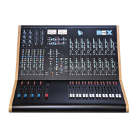
Optional Work Station-Producer’s Desk ................................................ 11
Channel Signal Path Architecture ................................................... 12
Channel Input Selection ....................................................................... 12
Channel Output Routing ....................................................................... 12
Direct Output .................................................................................... 12
Multitrack Buses ................................................................................ 13
Stereo Program Buses ........................................................................ 13
Panning ............................................................................................ 13
Session Signal Flow .............................................................................. 13
Small Fader to Multitrack .................................................................... 14
Large Fader to Multitrack .................................................................... 15
Signal Flow Block Diagram ................................................................... 15
Fader Bypass ........................................................................................ 15
Channel Strip Overview .................................................................. 16
Channel Input ................................................................................. 17
Upper 200 Slot...................................................................................... 17
212 Mic Preamp ................................................................................. 17
205 Direct Input ................................................................................ 18
Channel Input Patch Points .................................................................. 19
Channel Signal Processing .............................................................. 21
Lower 200 Slot ..................................................................................... 21
225 Compressor/Limiter ..................................................................... 21
235 Noise Gate/ Expander .................................................................. 22
215 High-Pass, Low-Pass Sweep Filter .................................................. 24
500 Series Equalizer Slot ...................................................................... 24
550A Discrete 3-Band Equalizer ........................................................... 25
550b Discrete 4-Band EQ .................................................................... 26
560 10-Band Graphic Equalizer ............................................................ 27
565 Filter Bank .................................................................................. 28
Channel Signal Processing Patch Points ............................................... 28
Channel Insert Patch Points ................................................................. 29
Lower 200 Slot Patch Points ................................................................ 29