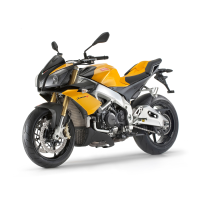
TABLE D1 - FRONT SPEED SENSOR
1. Cable grommet
2. Rubber clamp
3. Clamp
TABLE E
1. Speed sensor cable harness routing inside the
cable grommet and between throttle cables and
frame
•
Ensure that the cable grommet is not
interfering with the steering damper
during its movement
2. Right switch cable harness routing
3. Rubber clamp
4. Front stop switch cable harness routing
5. Main cable harness routing
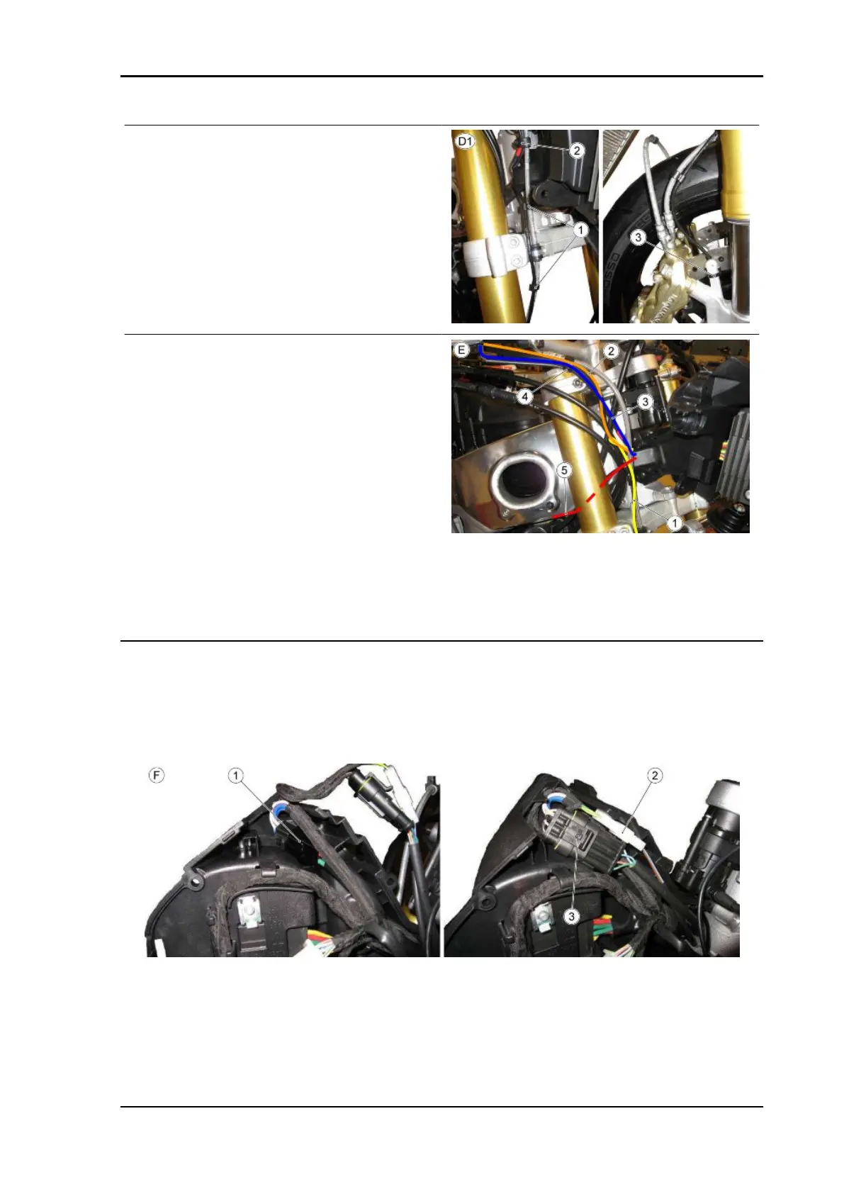
TABLE F - INSTRUMENT HOLDER SUPPORT
•
First connect the regulator connector (1) and place it as shown in the figure
•
Connect the stop connector (2) and then the right light switch connector (3) and place them
as shown in the figure.
TUONO V4 R a-PRC ABS Electrical system
ELE SYS - 105

 Loading...