TABLE F1 - INSTRUMENT HOLDER SUPPORT
•
Place the branch (1) in the correspond-
ing tongues as shown in the figure
•
Fit the front ABS sensor (2) as shown
in the figure
•
Place the clamps (3) to then fasten the
main cable harness.
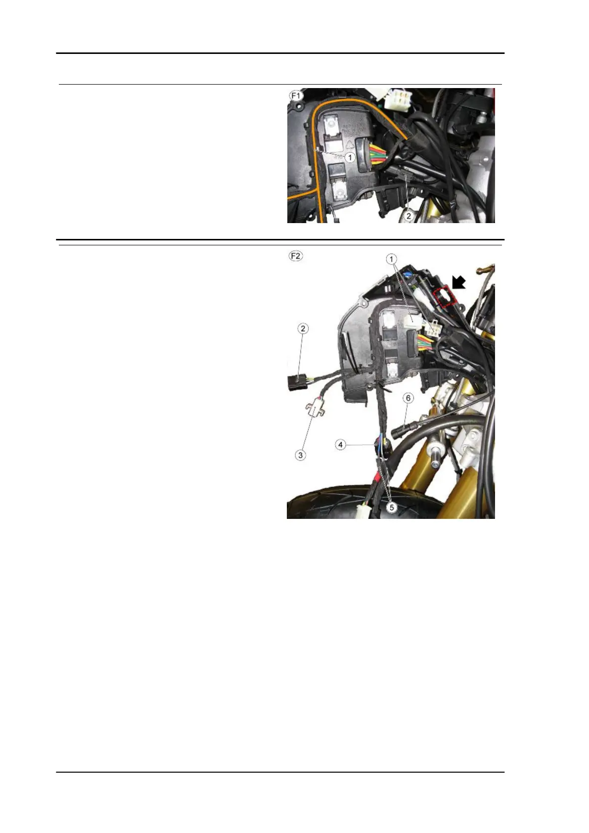
TABLE F2 - INSTRUMENT HOLDER SUPPORT
•
Tighten the clamps previously fitted
•
Keep the area in the dotted line free
from cables
1. Left light switch connectors
2. Lights relay connector
3. Front headlight connector
4. CLF control unit connector
5. Horn terminals
6. Immobilizer antenna connector
Electrical system TUONO V4 R a-PRC ABS
ELE SYS - 106

 Loading...