Programmers Model
ARM DDI 0363G Copyright © 2006-2011 ARM Limited. All rights reserved. 3-19
ID073015 Non-Confidential
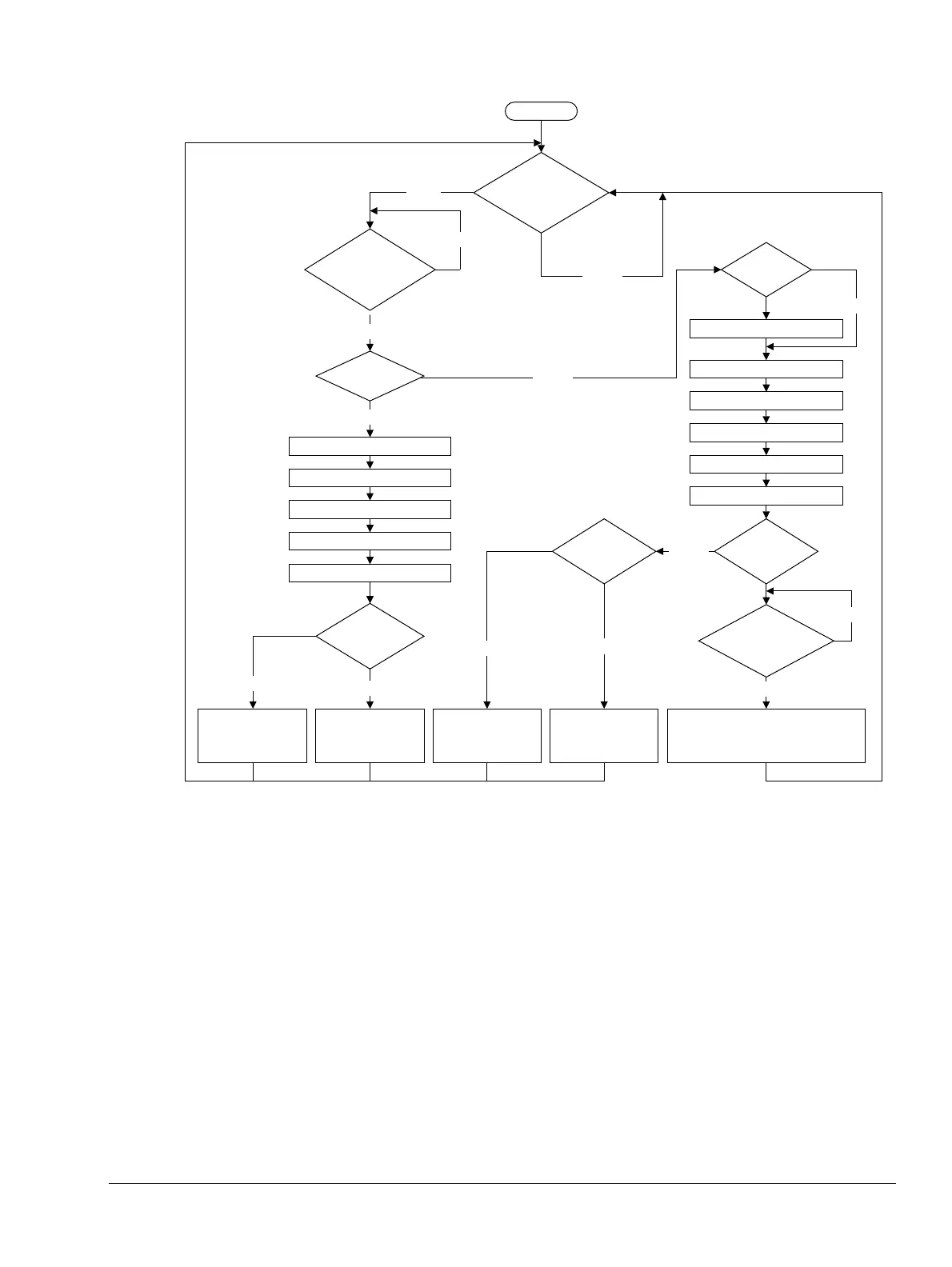
Figure 3-5 Interrupt entry sequence
For information on the I and F bits that Figure 3-5 shows, see Program status registers on
page 3-9. For information on the V and VE bits that Figure 3-5 shows, see c1, System Control
Register on page 4-37.
LR_fiq = RA+4
CPSR[4:0] = FIQ mode
CPSR[5] = TE
CPSR[7] = 1, CPSR[6] = 1
SPSR_fiq = CPSR
V==1
FALSE
TRUE
FALSE
!((nFIQ||F)
&&
(nIRQ||I))
!(nFIQ||F)
VE==1
FALSE
V==1
TRUE
PC[31:0] = Handler address
provided by VIC
Acknowledge address to VIC
TRUE
FALSE
Is VIC ready to
provide handler
address?
FALSE
TRUE
TRUE
Start handshake with VIC
LR_irq = RA+4
SPSR_irq = CPSR
CPSR[4:0] = IRQ mode
FALSE
CPSR[7] = 1
CPSR[5] = TE
VE==1
PC[31:0] =
0x0000001C
PC[31:0] =
0xFFFF001C
PC[31:0] =
0xFFFF0018
PC[31:0] =
0x00000018
!VE || VIC
handshake
complete
FALSE
Start
TRUE
TRUE
TRUE
FALSE