Note: Non-integer TC time base settings 23.976 and 29.97 are always counted
as non-dropframe time code.
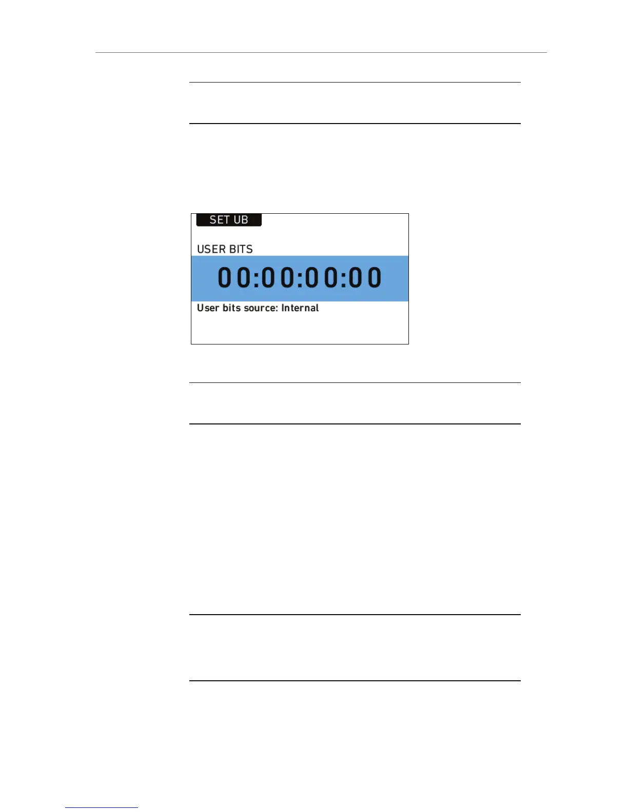
USER BITS
Press the USER BITS screen button to access the USER BITS screen.
For each user bit, values from 0 to 9 and A to F can be set.
Press the SET UB button to start editing the user bits values.
Figure 61: USER BITS screen
Note: On HD-SDI out, the last two digits of the user bits contain the Variflag,
therefore the last two user bits cannot be set by the user.
11.1.4.2 INFO
STATUS Info
The STATUS INFO screen displays information about the current state
of the camera system. System state: Good means that all components in
the ALEXA are functioning normally. Other messages can contain error
messages prefixed with E:, or warnings prefixed with W:. For more
information about error messages and warnings, see A.4 Error
Messages and Warnings in the Appendix.
Press the SAVE TO SD button to save a system log to the SD card. This
may take up to one minute.
Note: It is only necessary to save a system log if the camera experiences
multiple error messages or other abnormal behavior. The system log is not a
human-readable file and should be sent to an ARRI Camera Service center for
analysis.
 Loading...