Product Description
DualWave Arthroscopy Pump User’s Guide
DFU-0212 Rev. 1 Page 11 of 54
2
2
.
.
2
2
.
.
3
3
AR-6480 Operator Display Messages and Iconography
The console’s operator display [5] provides information about the status of the AR-
6480 modes, pressure, and flow settings in real time. Table 3 describes each
message or button, cause and explanation when the pump is in the ready state.
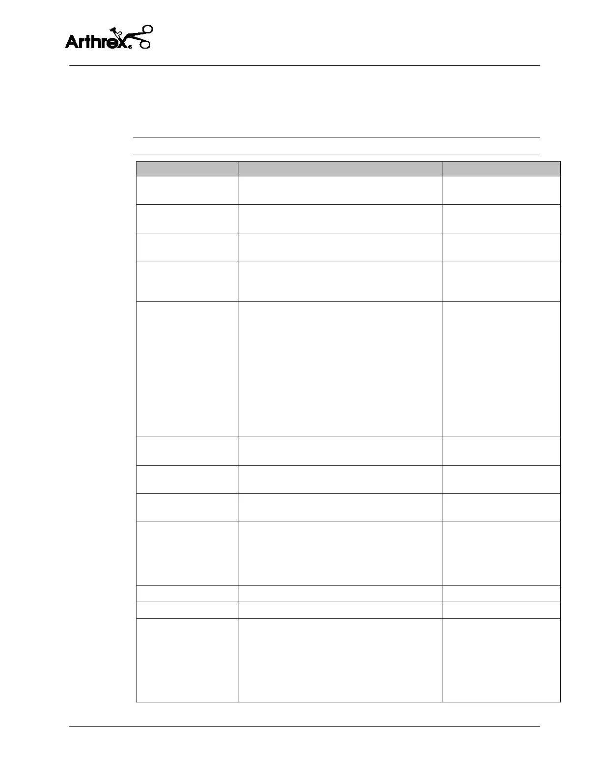
Table 3 AR-6480 Operator Display Messages and Iconography
Arthrex DualWave
Message appears when the AC mains power
switch is activated.
Power on message display.
** Tubing Out **
Message appears when tubing is not plugged
into the tubing sensor coupler [2].
Check tubing installation.
** Door Open **
Message appears when the roller housing door
[9] or [12] is open.
Roller housing door is not
closed.
** Over Pressure **
Message appears when the sensed pressure
exceeds over-pressure software limit of 300
mmHg.
Software overpressure
condition.
Critical Failure
Message appears on the first line of the operator
display if one of three conditions is met:
Failure Condition 1: ** Power Failure **
Appears if the power supply self-test fails when
the pump is turned on.
Failure Condition 2: ** OVP Detect Fail **
Appears if the hardware overpressure diagnostic
test fails when the pump is turned on.
Failure Condition 3: ** Sensor Failure **
Appears if the pump detects a problem with the
pressure sensors.
Critical failure, cannot
continue operation.
** Power Failure **
Message appears if the power supply self-test
fails when the pump is turned on.
Power supply test fails.
** OVP Detect Fail **
Message appears if the hardware overpressure
diagnostic test fails when the pump is turned on.
Hardware overpressure
diagnostic fails.
** Sensor Failure **
Message appears if the pump detects a problem
with the pressure sensors.
Sensor failure.
** Pressure Fault **
Message appears when the pump is unable to
reach a desired set pressure within a specific
amount of time. This typically indicates
improperly installed tubing or a split in the tube
from continuous use.
Insufficient pressure.
Remote Control Icon
Icon appears when the remote is attached. Remote connected.
Foot Pedal Icon
Icon appears when the foot pedal is attached. Foot pedal connected.
+ Button
The operator display shows the pressure reading
until the PRESSURE (+) button is pressed. Once
pressed, the displayed pressure reading will
change to the pressure setting. Each subsequent
press of the pressure button will increase the
pressure setting in increments of 5.
Pressure set increase.
 Loading...