Chapter 1
1-6
Rear Panel - Convenience in Connections
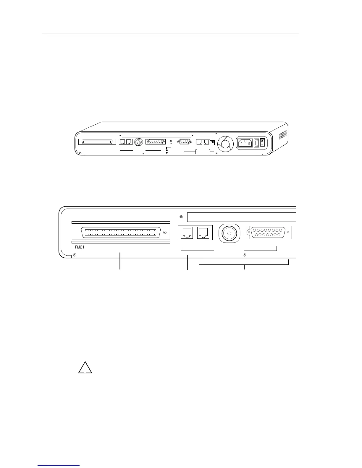
The rear panel of the AsantéHub is shown in Figure 1-3, below. It provides
TELCO device connections, 3-in-1 Uplink (network) connections, two LED
status indicators for the uplink, an RS-232 port for PC or terminal connection,
and the dedicated AMS link connectors, as well as the fan and power
hardware.
RJ21 10 BASE-T PORTS
IN or
OUT
AUI
PARTITION
TRAFFI C
RS232
RS4 85
12
THROUG
H
AMS LINK
UP=PC
DOWN=TE RMINAL
EN
D
3-IN-1 UPLINK
BNC
Spare Fuse in Fuse Holder
2A/250V Slow Blow Fuse
Replace Only With Fuse of Same Rating
Figure 1-3. Rear panel
Figure 1-4 illustrates the left side of the rear panel and describes its physical
features.
RJ21 10 BASE-T PORTS
BNC
Telco RJ-21 connector for connecting
to a punch-down block.
Used in place of the front panel RJ-45
ports.
Note: The Telco connector and the RJ-
45 ports cannot be used simultaneously.
RJ-45 IN port
Can be used as
thirteenth device
port if the 3-In-1
Uplink is not used
3-In-1 Uplink:
RJ-45/BNC/AUI autoswitch port
Used for the network link (uplink) to
other hubs or backbones.
Note: Keep BNC cable terminated
when hub is connected to
backbone.
AUI
IN
or OUT
3-IN-1 UPLINK
Figure 1-4 AsantéHub Rear Panel (left) - TELCO and Network
Connections
!
The right side of the rear panel is described in Figure 1-5.