Chapter 2
2-2
• Warning lights for four major error conditions.
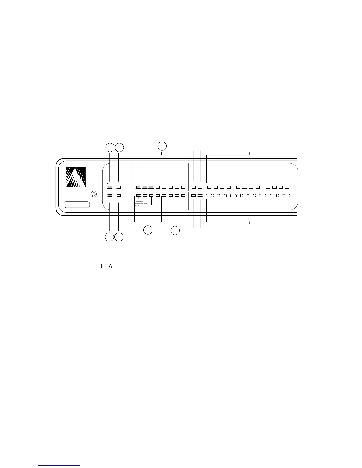
The figure below illustrates the front-panel LEDs during normal hub operation.
Note: The rear panel also features two LEDs marked PARTITION and TRAFFIC.
They duplicate the functions of the Partition Uplink and Link/Receive Uplink
LEDs, respectively. (The Partition Uplink and Link/Receive Uplink LEDs are
described in the following table.)
ASANTE
RESET
PWR CPU
SNMP MSG
UTILIZATION
%
1 3 5 10 203050 65+
1 3 5 10
COLLISION
%
1 2 3 4
5 6 7 8
9 10 11 12
PARTITION
LINK/RECEIVE
SNMP
UPLINK
Late Collision
Misaligned/CRC error
Runt/Fragmented packets
Short event/missing SFD
I I I I I I I I I I I
*
* *
* * * * *
*
* * * * * *
A
B
C
D
E
H
1
H
2
H
3
I
1
I
2
I
3
G
F
Figure 2-1. AsantéHub Front Panel, LEDs During Normal Operation
Table 2-1, on the following pages, lists the LEDs (starting from the left side of
the panel), and describes the meaning of each LED state.