Chapter 1
1-32
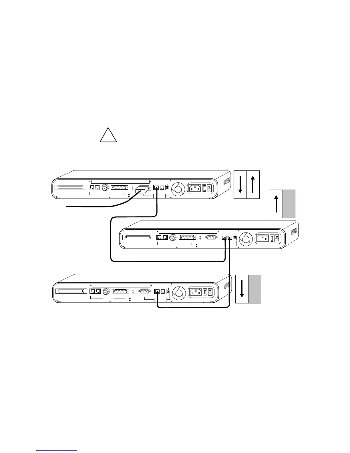
1. Connect a straight-through RJ-45 extension cable from a rear
panel AMS Link port on the first hub to a rear panel AMS Link
port on the second hub. See the figure below.
2. Terminate the hub at each end of the daisy-chain by flipping
rear panel Through/End DIP switch down (closed), unless you
used the other AMS Link port to connect to the network
management station.
!
The rule of thumb here is that if only one AMS Link
port or none is occupied by a cable, you must switch to end.
RJ21 10 BASE-T PORTS
IN or
OUT
AU
I
PARTITION
RS23
2
RS48
5
12
THROUGH
AMS
LINK
UP=PC
DOWN=TERMINAL
END
3-IN-1 UPLINK
BNC
Spare Fuse in Fuse Holder
2A/250 V Slow Blow Fuse
Replace Only With Fuse of Same Rating
TRAFFI C
RJ21 10 BASE-T PORTS
IN or
OUT
AU
I
PARTITION
RS23
2
RS4 8
5
12
THROUGH
AMS
LINK
UP=PC
DOWN=TE RMINAL
END
3-IN-1 UPLINK
BNC
Spare Fuse in Fuse Holder
2A/250V Slow Blow Fuse
Replace Only With Fuse of Same Rating
TRAFFI C
RJ21 10 BASE-T PORTS
IN or
OUT
AU
I
PARTITION
RS23
2
RS48
5
12
THROUGH
AMS
LINK
UP=PC
DOWN=TERMINAL
END
3-IN-1 UPLINK
BNC
Spare Fuse in Fuse Holder
2A/250V Slow Blow Fuse
Replace Only With Fuse of Same Rating
TRAFFI C
DIP Switches
DIP Switches
DIP Switches
To NMS
Figure 1-23. Wiring for Network Management Out-of-Band (NMS on RS-232 Port)