Pinouts & Cable Specifications
C-3
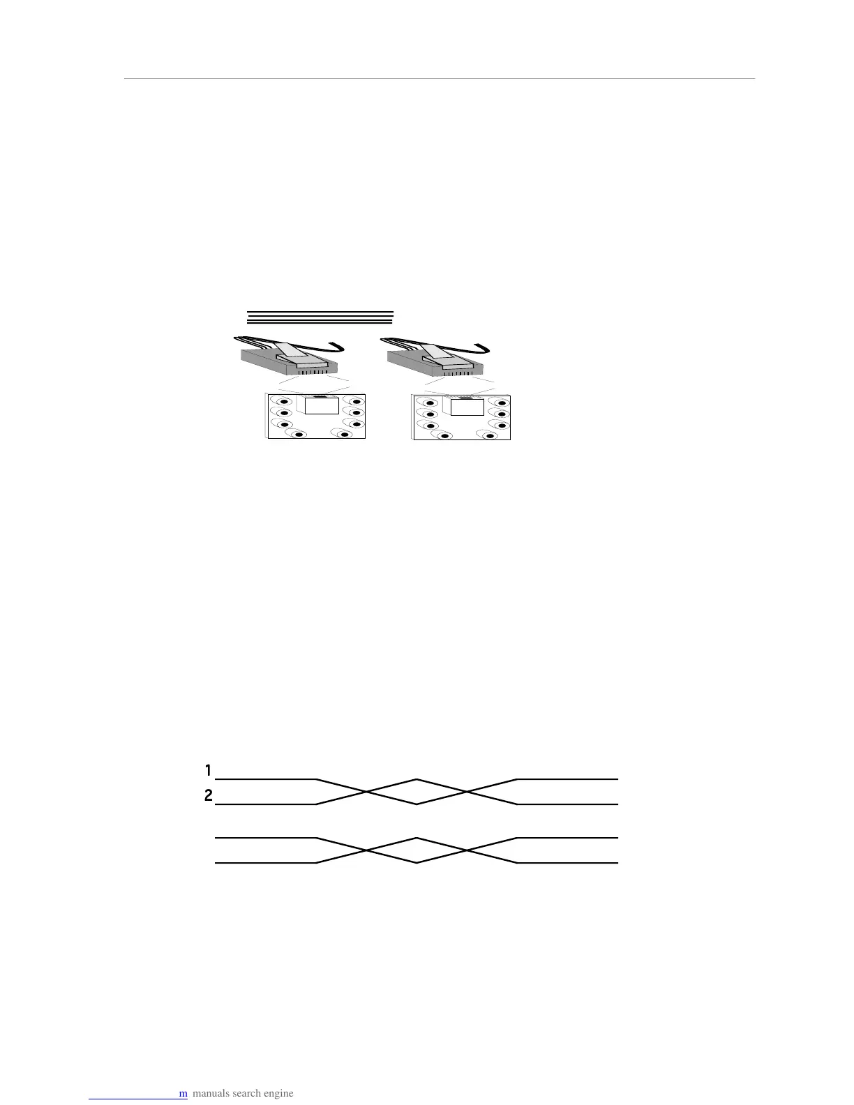
RJ-45 to RJ-45 Extension Cables
RJ-45 extension cables consist of two IS0 8877 8-pin modular jacks (RJ-45) on a
≤ 100 meter length of 24-gauge, solid conductor, unshielded twisted-pair wiring.
These pinouts describe the straight-through RJ-45 extension cable used in all
the RJ-45 ports on the hub. Note that the AMS Link ports use only pins 3 and 6.
However, to minimize cost and maximize consistency, use the pinouts below for
all twisted-pair extension cabling used in the network.
1 2 3 4 5 6 7 8
1
2
3
4
5
6
7
8
1 2 3 4 5 6 7 8
1
2
3
4
5
6
7
8
1
2
3
6
1
2
3
6
Rx
Rx
Tx
Tx
Rx
Rx
Tx
Tx
Figure C-4. RJ-45 to RJ-45 Pinouts
Front-Panel Modular Jack to RJ-45 Pinouts
The cabling between 8-pin twisted-pair modular jacks and the hub must be
straight-through, unshielded twisted-pair, 24 gauge, solid conductor unshielded
twisted-pair wire.
This figure illustrates in more detail the individual twisted-pairs that make up the
straight-through twisted-pair modular cable. Each pair of wires that make up the
eight wires attaching to pins 1 through 8 must be an individual twisted-pair. Note
that pins 1 and 2 are an individual twisted-pair, as are pins 3 and 6, 4 and 5, and 7
and 8. From the Hub to the 8-pin modular jack there must be an individual
twisted-pair for each pair of wires.
Figure C-5. Hub to Modular Jack Pinouts