Hardware Description
2-9
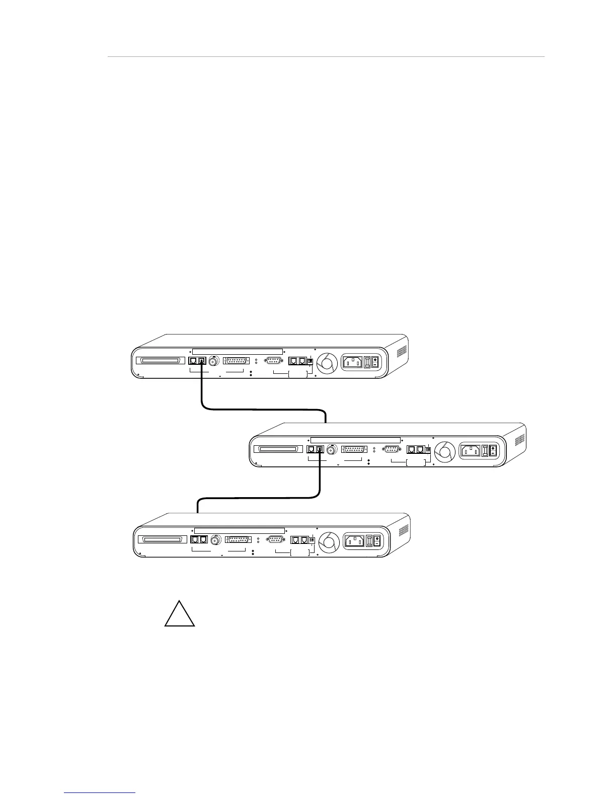
• Connect the next extension cable being between the rear
panel RJ-45 OUT port of hub #2, and a front panel port on hub
#3.
• Continue for additional hubs.
The second method can be used only if the network chain is ending (the daisy
chain does not need to be continued). This method preserves a front panel port
as an additional device connection. One end of the extension cable is connected
to the RJ-45 OUT (3-In-1 Uplink) connection. (Do not use the AMS Link jacks to
the right of the rear panel.) The other jack is connected to the rear panel RJ-45
IN (3-In-1 Uplink) port of the adjoining hub.
The network configuration must not exceed the maximum distance length or
device count guidelines as given in the 802.3 10BaseT specifications. See Table
3-1, “IEEE 802.3 Network Specifications,” for guidelines. See Appendix C,
“Pinouts and Cable Specifications,” for details on cable construction.
RJ21 10 BASE-T PORTS
IN or
OUT
AU
I
PARTITION
RS2 3
2
RS48
5
12
THROUGH
AMS
LINK
UP=PC
DOWN=TE RMINAL
END
3-IN-1 UPLINK
BNC
Spare Fuse in Fuse Holder
2A/250V Slow Blow Fuse
Replace Only With Fuse of Same Rating
TRAFFI C
RJ21 10 BASE-T PORTS
IN or
OUT
AU
I
PARTITION
RS2 3
2
RS48
5
12
THROUGH
AMS
LINK
UP=PC
DOWN=TE RMINAL
END
3-IN-1 UPLINK
BNC
Spare Fuse in Fuse Holder
2A/250V Slow Blow Fuse
Replace Only With Fuse of Same Ra ting
TRAFFI C
RJ21 10 BASE-T PORTS
IN or
OUT
AU
I
PA RTI TI ON
RS2 3
2
RS48
5
12
THROUGH
AMS
LINK
UP=PC
DOWN=TE RMINAL
END
3-IN-1 UPLINK
BNC
Spare Fuse in Fuse Holder
2A/250V Slow Blow Fuse
Replace Only With Fuse of Same Rating
TRAFFI C
RJ-45 To Front Panel Port
RJ-45 To Front Panel
Figure 2-3. Interconnecting Hubs via RJ-45 Ports
!
Note: You can never use more than one of the "3-in-1 Uplink" ports at
one time. Even in redundant backbone configurations, only one link can be
active at any given time.