Quick Start
1-23
If you are installing a multiple-hub network, you will go on to connect the
AMS link and network connections. In this case, also note that the network
management station must be connected to the hub at the end of the network
path.
Note: For further information, see Chapter 2, “Hardware Description,”
particularly Table 2-2, “Connectors and Their Usage;” or see Appendix C,
“Pinouts and Cable Specifications.”
What You Need
You need only the cable type appropriate for your network management
station (see the following figures). All cables described in this manual are
straight-through, except where otherwise noted.
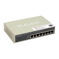
Interpreting Switch Settings
The switch settings in the figures refer to two small white DIP switches
besides the paired RJ-45 ports near the right-hand side of the rear panel.
Figure 1-16, below, illustrates DIP switches. Figure 1-17 illustrates the switch
settings key. These DIP switches affect (1) termination of the AMS link, and
(2) connection of terminal or PC to the RS-232 port on the hub.
A double-headed arrow indicates that the switch setting does not affect this
particular aspect of your configuration, but it may be affected by other
connections. Consult the switch settings for each step in the cabling
procedure.
12
END
THROUGH
PC NETWORK
MANAGEMENT
OR MODEM
TERMINAL
AMS LINK,
THROUGH
(NOT
TERMINATED)
AMS LINK,
END
(TERMINATED)
Figure 1-15. Switch Settings Key
!
Note: You should use the "Through" setting whenever you have both
AMS ports in use. The "End" setting should be used when one AMS link port
or no AMS link port is used.