TD 92579EN
15 February 2012 / Ver. H
Installation and Operation Manual
IP-DECT Base Station & IP-DECT Gateway (software version 5.0.x)
33
Pin the BS3x0/DB1 Cable
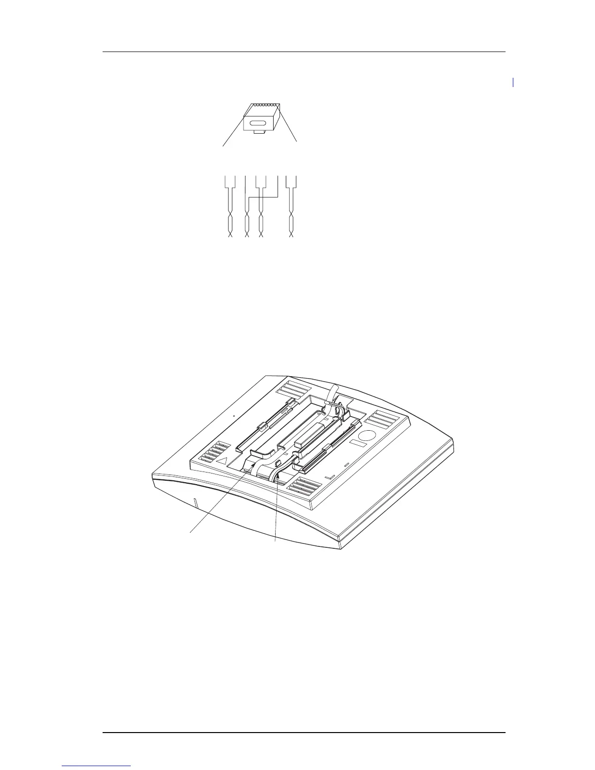
Figure 11.
odular jack
EPP-b
EPP-a
SC1-a
SC0-a
SC0-b
SC1-b
NC
NC
NC
=
Not Connected
EPP
=
Express Power Pairs
SC = Serial Channel
008
15432678
Figure 14. Connector pinning of the Data connector
IMPORTANT: If local
power supply is used, the EPP cable pair must NOT be connected.
5.2.8 Connect the Base Station Cables
1 Only for IPBS1: If it is required that the cables e
nter the base station centrally from
above, guide the cables through the recess in the middle of the base station as
shown below.
2 Plug the modular jack of the data cable into one of the data/power connectors.
3 When an AC-adapter is used:
• Plug the modular jack of the AC-adapter in one of the data/power connectors.
• Plug the AC-adapter into a
wall-outlet.
5.2.9 Mount the Base Station
Hold the base station flat against the mounting bracket and move it downwards until it
clicks, se
e below.
Power
cable