107
Commands
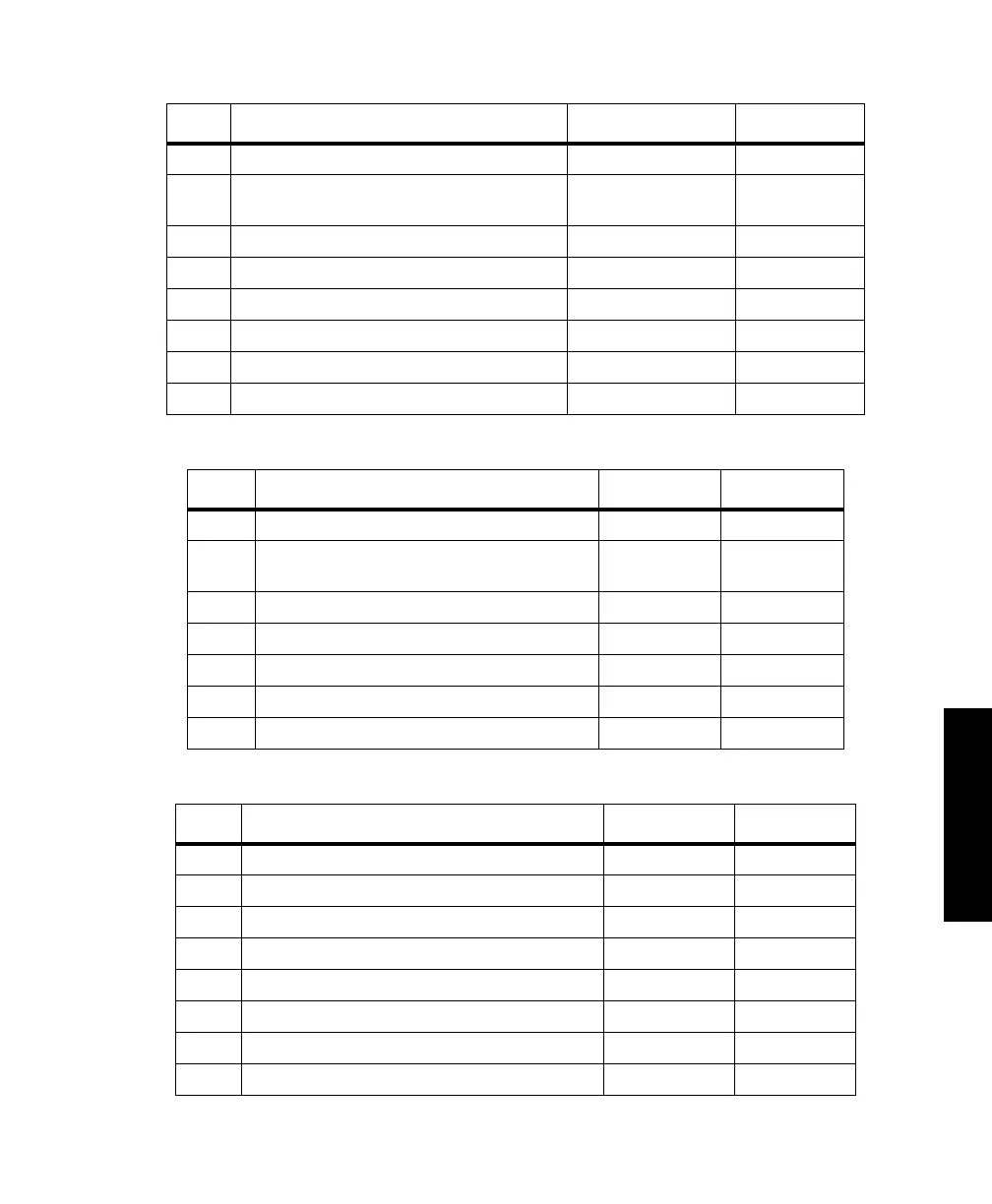
Table 4.49. UDG Structure for Oblique Mercator
Field Description Range / Name Units
s1 Map projection type OM83 n/a
d2 Number of parameters for the selected
projection
6n/a
f3 Azimuth of the skew axis ±1800000.0000 ddmmss.ssss
f4 Scale factor at center of projection 0.5 to 1.5 n/a
f5 Longitude of the grid origin of the projection ±1800000.0000 ddmmss.sss
f6 Latitude of the grid origin of the projection ±900000.0000 ddmmss.sss
f7 False easting ±10,000,000 meters
f8 False northing ±10,000,000 meters
Table 4.50. UDG Structure for Stereographic (Polar and Oblique)
Field Description Range / Name Units
s1 Map projection type STER n/a
d2 Number of parameters for the selected
projection
5n/a
f3 Latitude of the grid origin of the projection ±900000.0000 ddmmss.sss
f4 Longitude of the grid origin of the projection ±1800000.0000 ddmmss.sss
f5 Scale factor at center of projection 0.5 to 1.5 n/a
f6 False easting ±10,000,000 meters
f7 False northing ±10,000,000 meters
Table 4.51. UDG Structure for Lambert Conformal SPC83 (2 Std.Parallels)
Field Description Range / Name Units
s1 Map projection type LC83 n/a
d2 Number of parameters for the selected projection 6 n/a
f3 Latitude of Southern Standard parallel ±900000.0000 ddmmss.ssss
f4 Latitude of Northern Standard parallel ±900000.0000 ddmmss.ssss
f5 Longitude of the grid origin of the projection ±1800000.0000 ddmmss.ssss
f6 Latitude of the grid origin of the projection ±900000.0000 ddmmss.ssss
f7 False Easting ±10,000,000 meters
f8 False Northing ±10,000,000 meters
G12RevD.book Page 107 Tuesday, April 2, 2002 4:33 PM