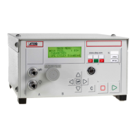
Chapter 1 – Installation of the instrument
UM-18400E-U ATEQ F580 User manual Page 16/168
4.3.3. 2) Printer link
1
6
5
9
SubD 9 pins male base
Pin 1 Not used Pin 6 Not used
Pin 2 RXD Data reception Pin 7 RTS request to send
Pin 3 TXD Data emission Pin 8 CTS clear to send
Pin 4 Not used Pin 9 Not used
Pin 5 Ground
4.3.3. 3) Examples of RS232 cables
1
2
3
4
5
6
7
8
9
1
2
3
4
5
6
7
8
9
ATEQ
Operator
9 pin SubD
connector
9 pin SubD
connector
RX
TX
GND
RTS
CTS
RX
TX
GND
RTS
CTS
1
2
3
4
5
6
7
8
9
1
2
3
4
5
6
7
8
ATEQ
Operator
25
9 pin SubD
connector
25 pin SubD
connector
RX
TX
GND
RTS
CTS
RX
TX
GND
RTS
CTS
4.3.4. J6 connector RS232 (remote control)
2
1
4
3
For connection of an intelligent remote control.
(Lumberg type female connector).
Pin 1 Network (TXD) Pin 3 Network (RXD)
Pin 2 + 24V voltage Pin 4 0V Earth / Ground
4.3.5. Central "PIN service" button
In the event of Winateq network management, this button
allows the confirmation of the centrals’ presence in the
network.
4.3.6. Head "PIN service" button
This button allows the confirmation of the heads' presence in
tne network in the hoped order.