Manual, F/T Sensor, Data Acquisition (DAQ) Systems
Document #9620-05-DAQ.indd-20
Pinnacle Park • 1031 Goodworth Drive • Apex, NC 27539 • Tel: 919.772.0115 • Fax: 919.772.8259 • www.ati-ia.com • Email: info@ati-ia.com
35
6. Once the DAQ system is set up and functioning properly, the transducer can be installed. While
monitoring strain gage voltages for saturation errors with the ATI Demo software, install the transducer
on the robot or any selected device to prevent exceeding the transducer’s overload rating. In the Data
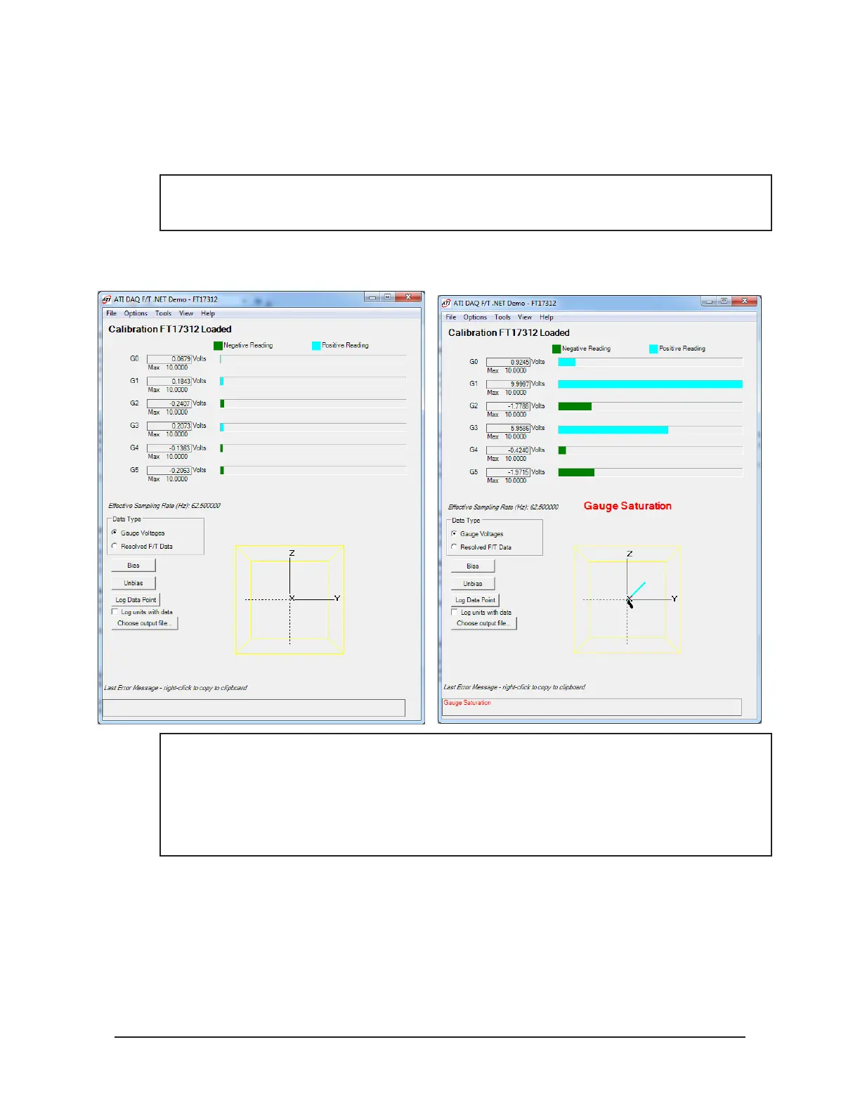
Type eld select Gauge Voltages to monitor the gage voltages during installation. If a gage saturation
error is reported, stop applying force immediately and wait until error clears.
NOTICE: A saturation error will be generated when the transducer or data acquisition hardware
has a load or signal outside of its sensing range. The screen on the right in Figure 4.13 shows a
Gauge Saturation error.
Figure 4.13—Set Gauge Voltages Data Type and Monitor for Gauge Saturation Errors
Screen Showing No Errors Screen Showing Gauge Saturation Error
NOTICE: Do not exceed the transducer’s overload ratings. Smaller transducers can be
irreparably damaged in the application of small loads when using tools (moment arm increases
applied loads), in the process of mounting the transducer. Be sure to use the demo application
to monitor the transducer for gage saturation errors during installation. If an error is indicated,
stop from applying force to the transducer and wait until the error clears before continuing
installation. If error does not clear, it may indicate loss of power or that the overload value has
been exceeded.
7. For the proper installation of the transducer to the robot or other device, refer to the 9620-05-Transducer
Section— Installation, Operation Manual.
8. After Installation of the transducer is complete, select resolved F/T Data in the Data Type box. The
system is ready for operation.
 Loading...
