2. The Program and Data Addressing Modes
The AVR
®
Enhanced RISC microcontroller supports powerful and efficient addressing modes for access
to the Program memory (Flash) and Data memory (SRAM, Register file, I/O Memory, and Extended I/O
Memory). This chapter describes the various addressing modes supported by the AVR architecture. In the
following figures, OP means the operation code part of the instruction word. To simplify, not all figures
show the exact location of the addressing bits. To generalize, the abstract terms RAMEND and
FLASHEND have been used to represent the highest location in data and program space, respectively.
Note: Not all addressing modes are present in all devices. Refer to the device specific instruction
summary.
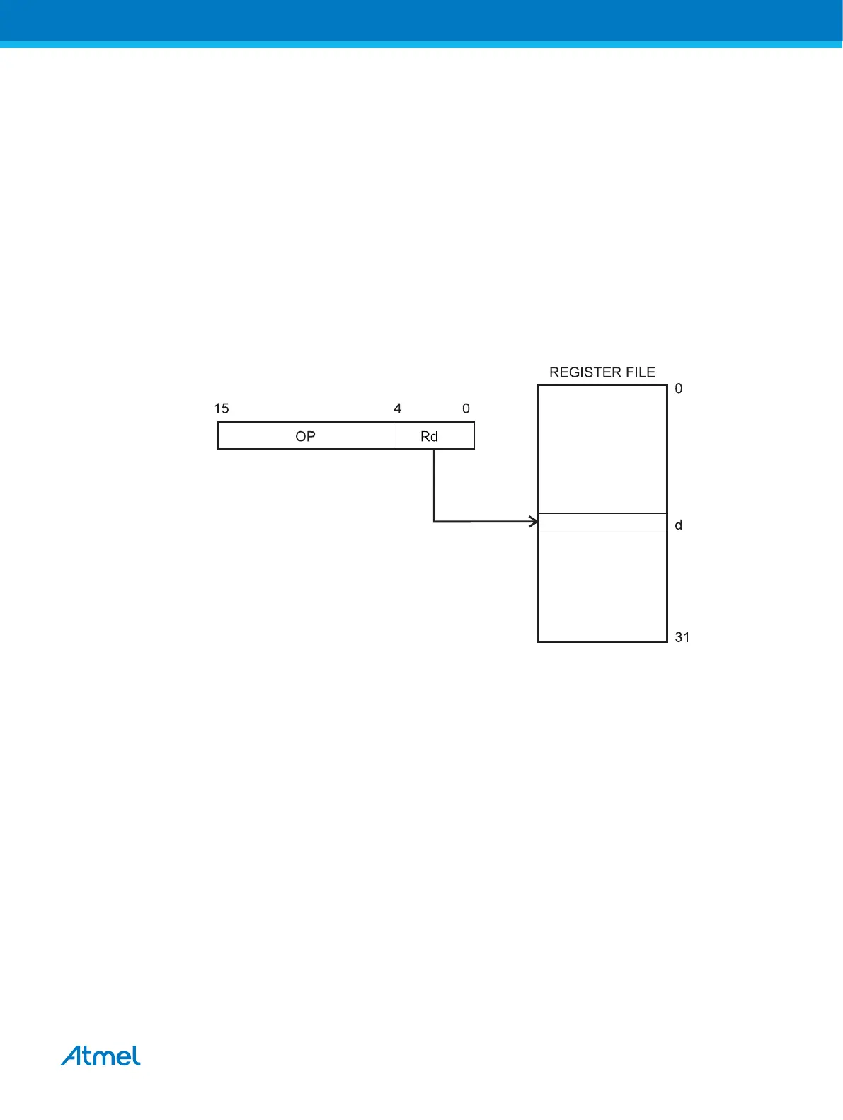
2.1. Register Direct, Single Register Rd
Figure 2-1. Direct Single Register Addressing
The operand is contained in register d (Rd).
Atmel AVR Instruction Set Manual [OTHER]
Atmel-0856L-AVR-Instruction-Set-Manual_Other-11/2016
14