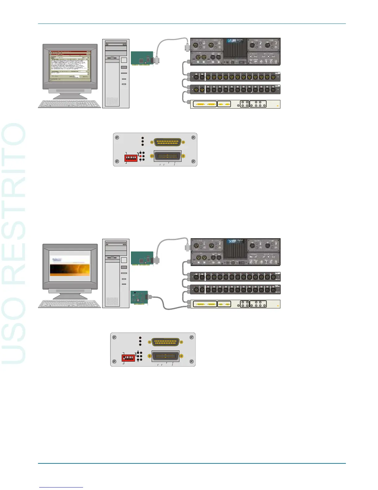
To use APIB to con trol your in stru ment, se lect APIB on the rear-panel
switch as shown in Fig ure 68 (left-most switch clicked up to “1”), and con -
nect a ca ble from the APIB in ter face card on the con trol ling com puter to the
in stru ment’s APIB port.
To use GPIB to con trol your in stru ment, con nect an ap pro pri ate ca ble from
the GPIB in ter face card on the con trol ling PC to the in stru ment’s GPIB port,
and se lect GPIB on the rear-panel switch as shown in Fig ure 69 (left-most
DIP switch clicked down to “0”). An LED will light to in di cate that GPIB is
se lected.
The GPIB Software Development Process Chapter 7: GPIB Configuration
Getting Started with Your 2700 Series Instrument 95
Input and Output Switchers
SYS-2722-192k instrument in APIB control mode
AP2700 Control Software
GPIB
Cable
(inactive)
GPIB Interface
Card
APIB
Cable
APIB
Interface Card
CAT II
CAT II
DCX-127 Multifunction Accessory: DC measurement
and Generation, Utility Static Digital Input and Output
Instrument controlled
by AP2700 running on PC.
Instrument set to APIB
mode. GPIB control inactive.
Rear-panel DIP switch
set UP to select APIB mode.
AUDIO PRECISION
INTERFACE BUS (APIB)
ERR
MAV
LA
RESET
RDNG
RDY
ADDRESSED
TA
SRQ
GPIB
GPIB
IEEE-488.2 (GPIB)
4
0
1
2 18 16
APIB
ADDRESS
RL0, PP0, DC1, DT1, C0, E2
SH1, AH1, T6, TE0, L4, LE0, SR1,
Figure 70. Control bus connections to 2700 series instrument with GPIB option in APIB
control mode. PC APIB cable connected first to switcher and DCX-127, then connected to
the instrument APIB port.
Input and Output Switchers
SYS-2722-192k in GPIB control mode
GPIB Control Software
GPIB
Cable
GPIB Interface
Card
APIB
Cable
SWR-2122
A B 1 2 3 4 5 6 7 8 9 10 11 12
CAT II
SWR-2122
A B 1 2 3 4 5 6 7 8 9 10 11 12
CAT II
DCX-127 Multifunction Accessory: DC measurement
and Generation, Utility Static Digital Input and Output
Instrument controlled by GPIB
running on controller PC.
2700 Series instrument set to
GPIB mode. Other APIB instruments
controlled via 2700 Series instrument.
Rear-panel DIP switch
set DOWN to select GPIB mode
AUDIO PRECISION
INTERFACE BUS (APIB)
ERR
MAV
LA
RESET
RDNG
RDY
ADDRESSED
TA
SRQ
GPIB
GPIB
IEEE-488.2 (GPIB)
4
0
1
2 18 16
APIB
ADDRESS
RL0, PP0, DC1, DT1, C0, E2
SH1, AH1, T6, TE0, L4, LE0, SR1,
Figure 71. Control bus connections to 2700 series instrument with GPIB option in GPIB
control mode. Switcher and DCX-127 connected to the instrument APIB port.