Narrow Band Amplitude
Frequency Range <10 Hz to 47% of Sample Rate
[10 Hz–22.56 kHz at 48 ks/s].
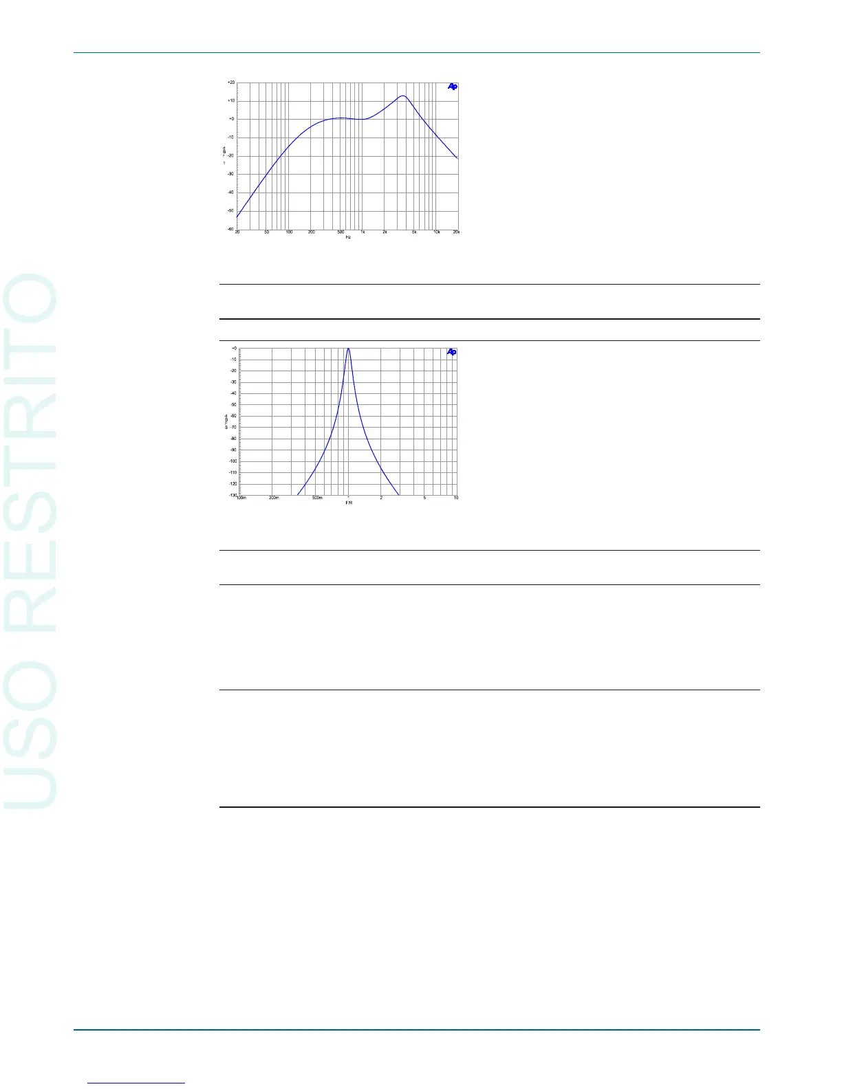
Filter Shape 10-pole, Q=19 (BW = 5.3% of f
o
). –see Figure 59
THD+N Measurements
Frequency Range <10 Hz to 47% of Sample Rate
[10 Hz–22.56 kHz at 48 ks/s].
High pass Filters <10 Hz (4-pole),
22 Hz (4-pole),
100 Hz (4-pole),
400 Hz (4-pole Butterworth).
Low pass Filters F
S
/2 (maximum bandwidth),
20 kHz (6-pole elliptic),
15 kHz (6-pole elliptic).
Weighting Filters ANSI-IEC “A” weighting, per IEC Rec 179,
CCIR QPk per IEC468 (CCIR),
CCIR RMS per AES17,
C-message per IEEE Std 743-1978,
CCITT per CCITT Rec. O.41,
“F” weighting corresponding to 15 phon loudness
contour, –see Figure 29
HI-2 Harmonic weighting.
Chapter 6: Specifications DSP Analysis of Analog Signals
72 Getting Started with Your 2700 Series Instrument
Figure 58. Digital Analyzer
F-weighting curve.
Figure 59. Digital Domain
Bandpass filter response.