Main Power Switch: Press this switch to apply power to the
AVR21EN. When the switch is pressed in, the unit is placed in a
Standby mode, as indicated by the light in the
Standby/On Button
1
turning red. The switch MUST be pressed in to operate the unit.
To turn the unit off and prevent the use of the remote control, this
switch should be pressed until it pops out from the front panel.
NOTE: This switch is normally left in the “ON” position.
1 Standby/On Button: When the Main Power Switch is pressed
in so that it is in the “ON” position, press this button to turn the
AVR21EN on. When the unit is in the Standby mode, the light in
the middle of the button is red. When the unit is on, the light in
the button is green.
2 Headphone Jack: This jack may be used to listen to the
AVR21EN’s output through a pair of headphones. Be certain that
the headphones have a standard 1/4" stereo phone plug, or that
you use an adapter, as needed, to convert the plug on your head-
phones to the 1/4" jack used on the AVR. When the headphone
jack is in use, the Main Room speakers will automatically be turned
off and the unit will output a standard stereo signal. You may also
use one of the Dolby Headphone modes for an enhanced listening
experience. For more information on headphone listening, see
the
Main Room Operation/Volume and Tone Control section.
3 Surround Mode Group Selector: Press this button to select the
top-level group of surround modes. Each press of the button will
select one of the surround mode categories. Once the button is
pressed so that the name of the desired surround mode category
appears in the on-screen display and in the
Lower Display Line
, press the Surround Mode Selector 4 to cycle through the
individual modes available. For example, press this button to select
Dolby modes, and then press the
Surround Mode Selector 4 to
choose from the various mode options.
4 Surround Mode Selector: Press this button to select from
among the available surround mode options for the surround
mode category selected. The specific modes will vary based on the
number of speakers available, the surround mode category and
whether the input source is digital or analog. For example, press
the
Surround Mode Group Selector 3 to select a category such
as Dolby or Logic 7, and then press this button to see the specific
mode choices that are available. For more information on mode
selection, see the
Main Room Operation/Surround Mode
Selection
and Digital Audio Playback sections.
5 Tuning Selector: Press the left side of the button to tune
lower-frequency stations and the right side of the button to
tune higher-frequency stations. When the tuner is in the
MANUAL/MONO mode, each tap of the selector will increase
or decrease the frequency by one increment. When the tuner
receives a strong-enough signal for adequate reception,
MANUAL TUNED will appear in the Lower Display Line
and in the on-screen display. When the tuner is in the
AUTO/STEREO mode, press the button once, and the tuner
will scan for a station with acceptable signal strength. When the
next higher – or lower – frequency station with a strong-enough
signal is tuned, the frequency scan will stop and the
Lower Display
Line
and the on-screen display will indicate AUTO TUNED.
When an FM Stereo station is tuned, the display will read
AUTO
ST TUNED.
See the Main Room Operation/Tuner Operation
section for more information on using the tuner.
6 Mode Adjust Down: Press to move down in menu options
when used with the
Tone , Speaker , Channel R, Digital
Sel Q
and Delay Mode P buttons. Within some selected modes,
press to adjust parameter values down.
7 Mode Set: This button has two functions. Press it to turn the
video processing circuits on or off, as indicated by
FAROUDJA:ON
or FAROUDJA:OFF messages in the Upper Display Line
and semi-OSD display. Press to select Mode subsettings when
adjusting Tone, Speaker, Channel, Digital Sel and Delay Mode
parameters. For example, press
Tone Mode . TONE IN/OUT
will appear on the Lower Display Line . Press one of the Mode
Adjust Buttons 68
to select TONE IN. Press Tone Mode
again. TREBLE MODE will appear in the lower display line.
Press the
Set Button 7. The numeric value for the treble adjust-
ment will appear in the
Lower Display Line . Either adjust the
value with one of the
Mode Adjust Buttons 68 or press the
Set Button 7 again. TREBLE MODE will again appear in the
Lower Display Line . Press Tone Mode again and BASS
MODE
will appear in the Lower Display Line . Repeat the
button press sequence to adjust Bass. This sequence of button
presses will allow you to change settings when using the
Tone ,
Speaker , Channel R, Digital Sel Q and Delay Mode P
buttons.
8 Mode Adjust Up: Press to move down in menu options when
used with the
Tone , Speaker , Channel R, Digital Sel Q
and Delay Mode P buttons. Within some selected Modes, press
to adjust parameter values up.
9 Tuner Band Selector: Pressing this button once will switch the
AVR to the Tuner mode. Pressing it again will switch between the
AM and FM frequency bands.
A Preset Station Selector: Press this button to scroll up or
down through the list of stations that have been entered into the
preset memory. See the
Main Room Operation/Tuner Operation
section for more information on tuner programming.
B Optimizer Mic Input: 3.5mm mini jack for use with the included
EzSet/EQ Microphone for calibrating room EQ, and speaker output
levels.
C Optical 3 Digital Input: Connect the optical digital output of
an audio or video product to this jack. Select Game/Cam as Source.
D Optical 3 Digital Output: Connect this jack to the optical digi-
tal audio input of a compatible digital recorder. Select a source
with digital audio for signal.
E Input Source Selector: Press this button to change the input
by scrolling up or down through the list of input sources.
F Coaxial 3 Digital Input/Output: Connect the coaxial digital
output of a digital audio product such as a portable audio player
or video game to this jack when switched as an input. Connect this
jack to the optical digital audio input of a compatible digital
recorder when switched as an output.
G Coaxial 3 – Input/Output Status Indicator: This LED indicator
will normally light green to show that the front-panel
Coaxial 3
Digital Input/Output Jack F
is operating as an input. When this
jack is configured for use as an output, the LED will turn red
to show that the jack may be used as an output for recording. See
the
Main Room Operation/Front Panel Connections section for
more information on configuring the front-panel jacks as outputs,
rather than inputs.
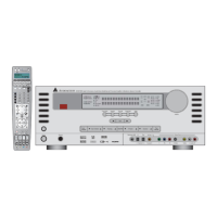
13
AVR21EN Front-Panel Features
 Loading...