Q Digital Input Selector: Press this button to begin the process
of selecting a digital source for use with the currently selected input.
Once the button has been pressed, use the
Mode Adjust Buttons
68
to choose the desired input and then press the Set Button
7
to enter the setting into the unit’s memory. See the Main Room
Operation/Surround Mode Selection, Digital Audio Playback
and Recording sections for more information on digital audio.
R Channel Adjust Selector: Press the button to begin the
process of adjusting the channel level outputs using the source
currently playing through your AVR. For complete information
on adjusting the channel output level, see the
Main Room
Operation/Output Level Trim Adjustment
section.
Speaker Selector: Press this button to begin the process of
configuring the AVR21EN for the type of speakers it is being used
with. For complete information on configuring the speaker settings,
see the
AVR21EN Configuration/Speaker Setup section.
Tone Mode Selector: This button controls the tone mode
settings, enabling adjustment of the bass and treble boost/cut.
You may also use it to take the tone controls out of the signal path
completely for “flat” response. The first press of the button displays
a
TONE IN message in the Lower Display Line and in the
on-screen display. To take the controls out of the signal path, press
either of the
Mode Adjust Buttons 68 until the display reads
TONE OUT. To change the bass or treble settings, press the
button again until the desired option appears in the
Lower
Display Line
and in the on-screen display and then press either
of the
Mode Adjust Buttons 68 to enter the desired boost or
cut setting. See the
Main Room Operation/Volume and Tone
Control
section for more information on the tone controls.
IR Remote Sensor Window: The sensor behind this window
receives infrared signals from the remote control. Aim the remote
at this area and do not block or cover it unless an external remote
sensor is installed.
H Tuner Mode Selector: Press this button to select Auto or
Manual tuning. When the button is pressed so that
AUTO/STEREO appears in the Upper Display Line , the
tuner will search for the next station with an acceptable signal
when the
Tuning Selector Button 5 is pressed. When the button
is pressed so that
MANUAL/MONO appears in the Upper
Display Line
, each press of the Tuning Selector Button 5
will increase the frequency by one increment. This button may
also be used to switch between Stereo and Mono modes for FM
radio reception. When weak reception is encountered, select the
Manual/Mono tuning mode. Press again to switch back to
Auto/Stereo mode. See the
Main Room Operation/Tuner
Operation
section for more information on using the tuner.
I Game/Cam Component Video Input: These component
video jacks may be used as either inputs or outputs for temporary
connection to video games or portable audio/video products such
as a camcorder. See the
Main Room Operation/Front-Panel
Connections
section for more information on switching these
jacks between an input and output.
J Game/Cam S-Video Input: This S-video jack may be used as
either an input or output for temporary connection to video games
or portable audio/video products such as a camcorder. See the
Main
Room Operation/Front-Panel Connections
section for more
information on switching these jacks between an input and output.
K Game/Cam Input/Output Status Indicator: This LED indicator
will normally light green to show that the front panel Game/Cam
Input/Output Jacks are operating as inputs. When these jacks are
configured for use as outputs, the LED will turn red to show that
the jacks may be used as an output for recording. See the
Main
Room Operation/Front-Panel Connections
section for more
information on configuring the front-panel jacks as outputs, rather
than inputs.
L Game/Cam Composite Video Input: This composite video
jack may be used as either an input or output for temporary
connection to video games or portable audio/video products such
as a camcorder. See the
Main Room Operation/Front-Panel
Connections
section for more information on switching these
jacks between an input and output.
M Game/Cam Line-Level Audio Inputs: These audio jacks may
be used as either inputs or outputs for temporary connection to
video games or portable audio/video products such as camcorders
and portable audio players. See the
Main Room Operation/
Front-Panel Connections
section for more information on switch-
ing these jacks between an input and output.
N Main Room Volume Control: Turn this knob clockwise to
increase the volume, counterclockwise to decrease the volume.
If the AVR21EN is muted, adjusting the volume control will
automatically release the unit from the silenced condition.
O Information Display: This display delivers messages and status
information to help you operate the AVR21EN. See the
Front-Panel
Information Display Features
section for a complete explanation
of the display.
P Delay Adjust Selector: Press this button to begin the process
of adjusting the delay settings. See the
Speaker Setup/Speaker
Distances
section for more information on delay adjustments.
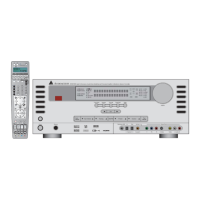
14
AVR21EN Front-Panel Features
 Loading...