Avid S6 Installation Guide46
Short Ethernet Cables for Knob Modules and Display Modules
(Systems with Two Knob Modules per Chassis and/or Display Modules Only)
If your system includes two Knob Modules in any chassis, take one of the included 12-inch long Ethernet cables and connect one
end of it to an available port on the interior of the Back Tie Plate. Repeat for all chassis that will have two Knob Modules.
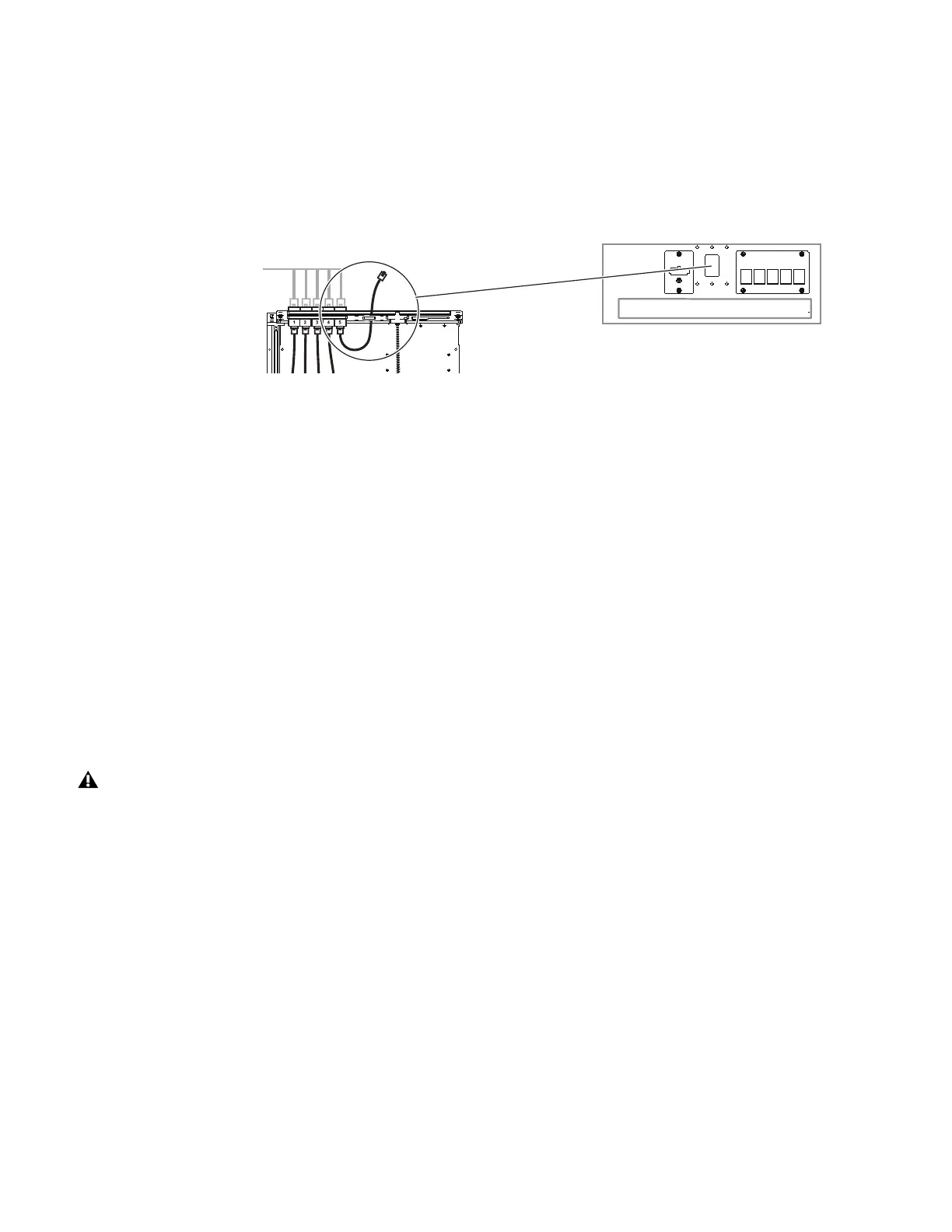
If your M40 or M10 Plus system includes one or more Display Modules, route a 12-inch Ethernet cable through the middle hole
on the back of the chassis as shown in Figure 28. Feed an available 2-pin power cable from the Cable Harness through the same
opening (you will connect these to the Display Module later).
Ethernet Cabling for Systems with Two Ethernet Switches
If your system includes 23 or more modules, two Ethernet switches are required. The two switches must be connected to each other
using a single Ethernet cable.
To connect two Ethernet switches to each other:
1 Feed one end of a the included single Ethernet cable through the opening in the back of either of the chassis containing an Ether-
net switch.
2 Connect it to an available port on the switch.
3 Run the cable through the triangular openings in the Rear Covers and connect it to an available port on the other switch.
Installing the Ethernet Cable for Workstations
To install an Ethernet cable for connecting to workstations:
1 Connect one end of the single Ethernet cable (included with the Ethernet switch) to an available port on the switch.
2 Guide the cable across the Rear Covers to the far left or right corner. Do not yet connect it to any workstations, routers, or
switches.
3 If you plan on connecting directly to multiple workstations, connect another Ethernet cable (not included) to an available port
on the switch and route it as described in the previous steps.
Figure 28. Routing a short Ethernet cable for a Display Module (2-pin power cable not shown)
Do not connect the system to any workstation, external routers, switches, or networks until after you have updated S6 system soft-
ware as explained later in this guide.
 Loading...
