5-24
Chapter 5. DETAILED DESCRIPTION OF EACH FUNCTION
Heat/Cool control
The Heat/Cool control related items, such as Heat/Cool, Heat/Cool control dead
zone, and Heat/Cool change point can be set.
However, when the control output type is R1 (motor drive relay output), the Heat/
Cool control is not enabled.
Item (Bank) Display Contents Initial value User level
Heat/Cool
(Setup bank)
0: Normal
1: Energy saving
0 Standard,
High function
Heat/Cool control dead
zone
(Setup bank)
-100.0 to +100.0% 0.0% Basic,
Standard,
High function
Heat/Cool change point
(Setup bank)
-10.0 to +110.0% 50.0% High function
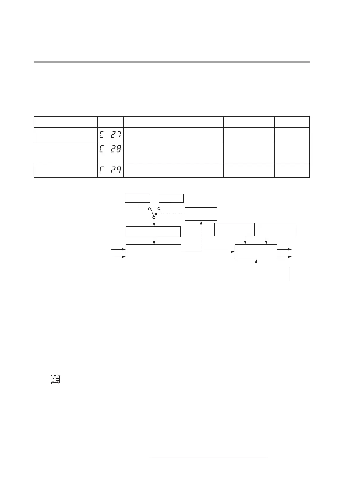
The following shows the Heat/Cool control calculation:
PID (heat) PID (cool)
Heat/Cool
PID (heat)
Constants oL, oH
PID (cool)
Constants oL, oH
Heat/Cool output
calculation
PID control
(Fixed at reverse action)
Heat/Cool control dead zone
Heat/Cool control change point
Constants P, I, d, rE
Cool MV
MV (PID control result)
• When [
C26
: Heat/Cool control] is set to [1: Enabled], the display and setting can
be made.
• When MV ≥ 50%, the control is changed to the PID (heat).
• When MV < 50%, the control is changed to the PID (cool).
• When [
C27
: Heat/Cool] is set to [1: Energy saving], the heat/cool change is
suppressed to indirectly obtain the energy saving effect. However, when [
C28
:
Heat/Cool control dead zone] is less than 0.0%, the energy saving effect cannot
be obtained.
• How the relationship between the output (heat) and output (cool) is made for the
PID control result (MV) is set.
Note
Heat/cool output
Formulas and limits for the heat/cool MV
“Deadband” in the explanation below refers to a heat/cool control dead zone.
The cool MV and the heat MV are determined by the following formulas and the
MV high and low limits.
Heat MV = (MV − heat/cool control change point − 0.5 × dead zone) × change rate
Cool MV = (heat/cool control change point − MV − 0.5 × dead zone) × change rate
Change rate =
100
Heat/cool control change point − 0.5 × dead zone