MagneW FLEX+/PLUS+ Electromagnetic Flowmeter Detector 1-1
Chapter 1 : Introduction
1.1 : Principle of operation
The owmeter consists of two parts: a detector which is mounted in the pipeline and
through which the measured liquid ows, and a converter which may be mounted
either integral with the detector or separately. The converter conditions and outputs
the electrical signal from the detector or separately. The converter conditions and
outputs the electrical signal from the detector.
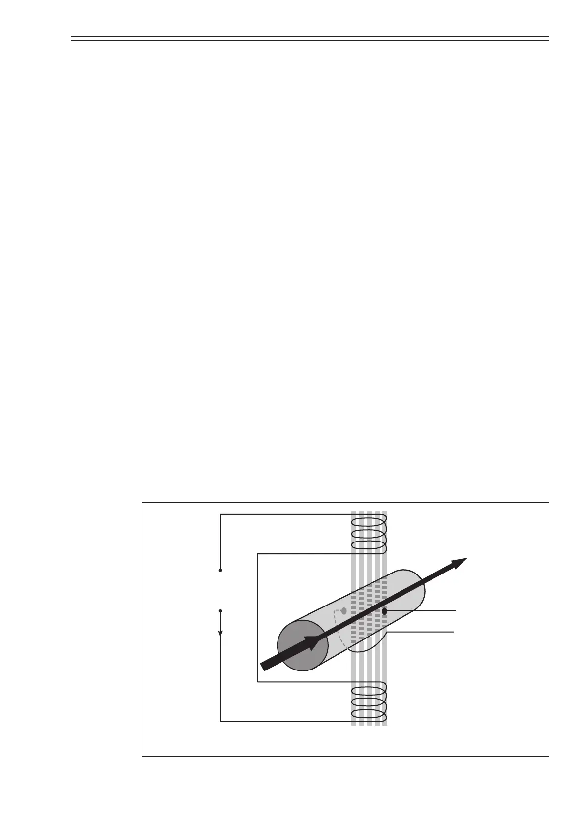
The owmeter works based on the principle of Faraday’s law of electromagnetic
induction, which states that if an electrical conductor, in this case the measured
conductive liquid, passes through a magnetic eld a small electromotive force (EMF)
is induced perpendicular to the eld and ow (refer to Figure 1-1).
Faraday’s law:
E = k BDV when
E = Induced voltage (EMF)
B = Strength of the magnetic eld
D = Conductor width (electrode spacing)
V = Velocity of the conductor
k = Correction factor
This induced EMF is proportional to the average ow rate and is detected by
two electrodes (E
1
and E
2
) mounted in the wall of the detector and then fed to the
converter.
The only variable in this application of Faraday’s law is the ow rate (V) of the
conductive measured liquid, because eld strength (B), is controlled constant and
electrode spacing (D) is xed.
Therefore, the output electromotive force is directly proportional to liquid ow rate,
resulting in the linear output of a magnetic owmeter.
Flow rate (V)
E1
E2
voltage
supply
Measuring fluid
Magnetic
field (B)
Figure 1-1 Faraday’s law