Azbil Corporation Installation
MagneW FLEX+/PLUS+ Electromagnetic Flowmeter Detector 2-51
5 mm
(0.2 inch)
C-wire
SA-wire
SB-wire
5 mm
(0.2 inch)
C-wire
SA-wire
SB-wire
A-wire
B-wire
tube
Conductive
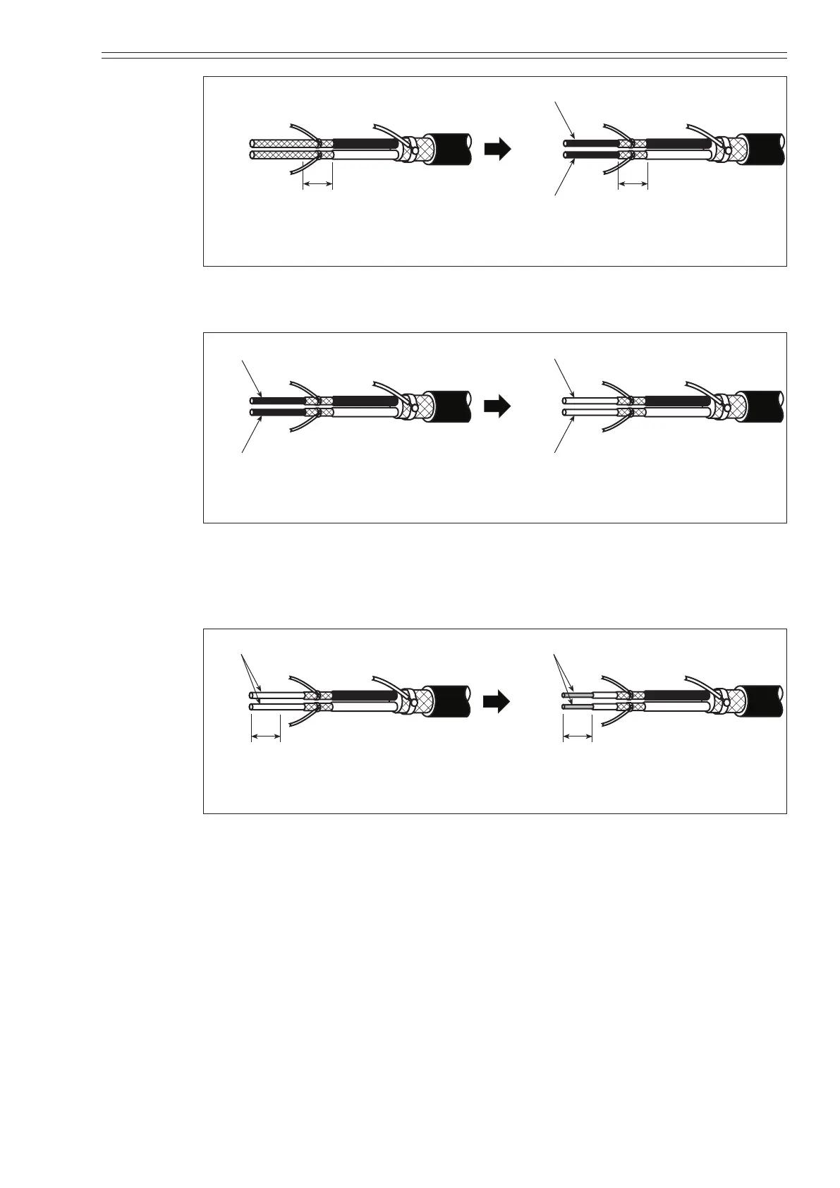
Figure 2-44 Trimming the inside shield
(9) Peel o the conductive tube (black) completely up to the inside shield.
C-wire
SA-wire
SB-wire
A-wire
B-wire
Insulator
C-wire
SA-wire
SB-wire
A-wire
B-wire
Conductive
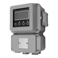
Figure 2-45 Removing the conductive tube
(10) Trim the insulator to within 5 mm (0.2 inch) from its end. Trim the other lead
wires (soldered to the shield sections) to the specied lengths so that each
conductive wire is exposed by 5 mm (0.2 inch).
5 mm
C-wire
SA-wire
SB-wire
5 mm
C-wire
SA-wire
SB-wire
A-wire
B-wire
Figure 2-46 Trimming the insulator
(11) Wind insulating tape around each inside shield and then around each outside
shield.
(12) Attach markers to the lead wires.
(13) Crimp the terminals onto each lead wire. Test each terminal by pulling on it to
make sure the terminal will not come o.
~Note
In some cases, the C -wire must be crimped together with either the
SA or SB lead wire. For further information, refer to the appropriate
operation manuals.