Installation Azbil Corporation
2-52 MagneW FLEX+/PLUS+ Electromagnetic Flowmeter Detector
Testing continuity
Test the continuity between the following terminals of the trimmed cables.
Table 2-10 Cable continuity
Terminals Resistance
A - A
0 W
B - B
C - C
Testing the insulation
Test the insulation between the following terminals using an insulation resistance
tester.
Table 2-11 Cable continuity
Terminals Resistance
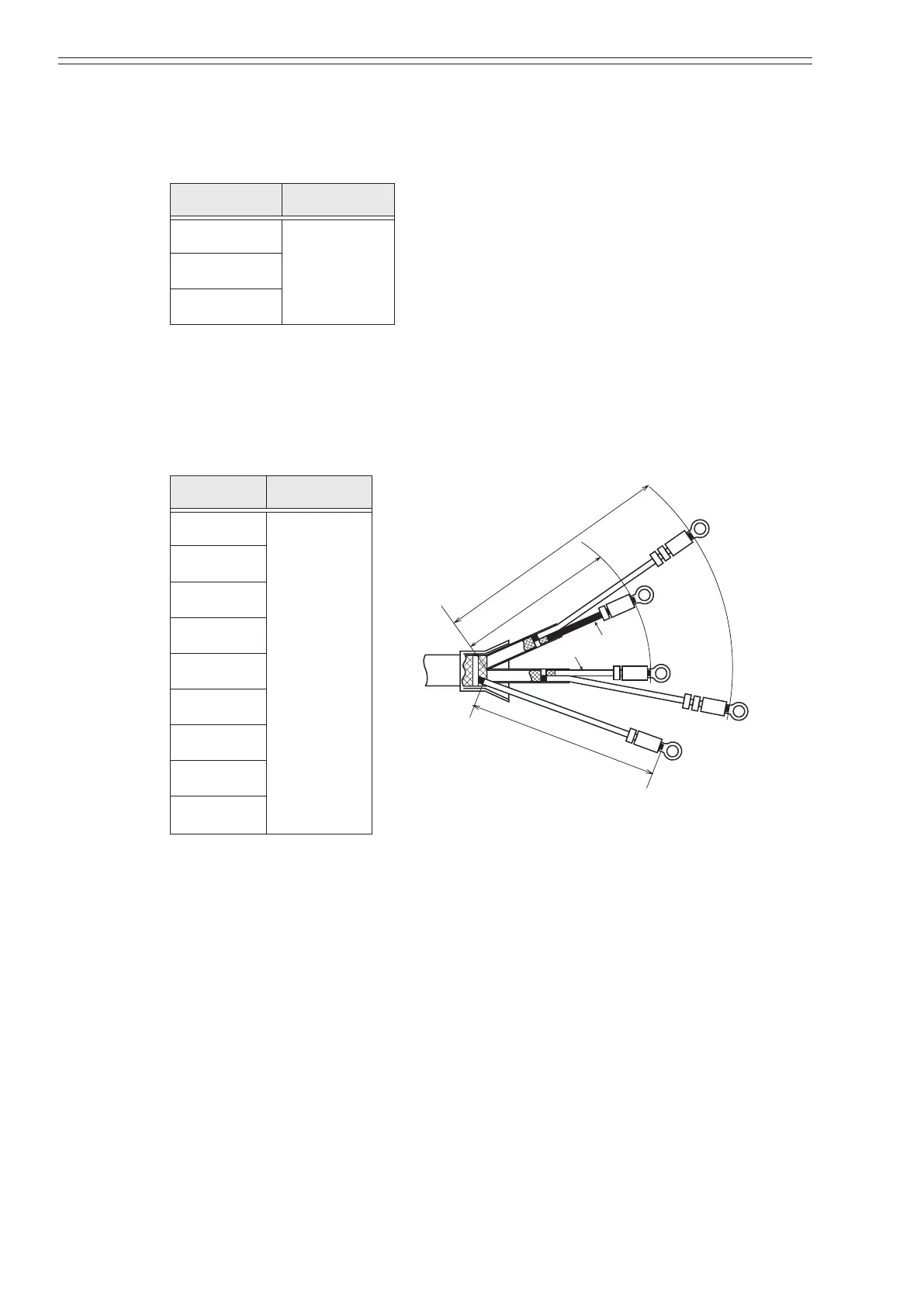
S
B
B
A
A
S
Black
White
C
SA
A
B
C
90 mm (3.54 inch)
60 mm (2.36 inch)
65 mm (2.56 inch)
Figure 2-47 Terminal connections
A - B
> 100 MW,
500 V DC
A - C
A - SA
A - SB
B - C
B - SA
B - SB
C - SA
C - SB