Installation Azbil Corporation
2-4 MagneW FLEX+/PLUS+ Electromagnetic Flowmeter Detector
2.3.1: Detector position
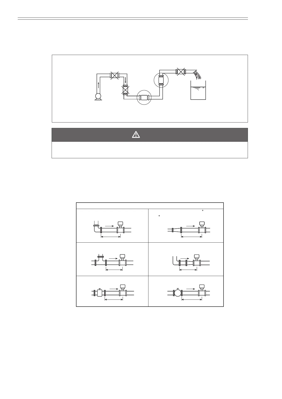
• Position the detector so that its inner detector passage is continuously lled with
the uid being measured. The following gure provides examples.
Bad
Air is easily trapped -
may not ll with uid
with uid
Good
Figure 2-1 Detector placement
CAUTION
The detector must be positioned as shown by the circled areas in the gure shown
above. If the pipe is not lled, output errors will occur.
• When measuring high viscosity uid, connecting the pipe to a vertical detector is
recommended (in order to secure an axial symmetrical ow).
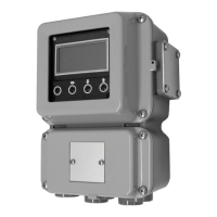
• Install a straight pipe section on the upstream side of the detector. The following
gure shows the length of the straight pipe section (D = nominal bore diameter of
the detector).
Upstream
> 5D
T-joint
Gate valve (Completely open)
Diffuser with cone angle >15
(<15 Considered straight pipe section)
Concentrator
(Considered straight pipe section)
Any type of valve
Right angle joint
Detector
> 5D
Detector Detector
> 10D
Detector
> 5D
Detector
> 5D
Detector
> 5D
Figure 2-2 Straight pipe section on upstream side of detector
• Although a pipe section is not necessary on the downstream side, secure a section
of at least 2D if eccentric ow appears.
• Select an installation site where there is no major pulsation or vibration (away
from a pump).
• Make sure that there is adequate space around the detector after installation to
perform maintenance.