Azbil Corporation Installation
MagneW FLEX+/PLUS+ Electromagnetic Flowmeter Detector 2-55
CAUTION
Be sure to use adequate solder so that contact failure will not occur between the
C -wire and the outside shield. If the soldering connection is insecure, noise is
generated due to contact resistance.
CAUTION
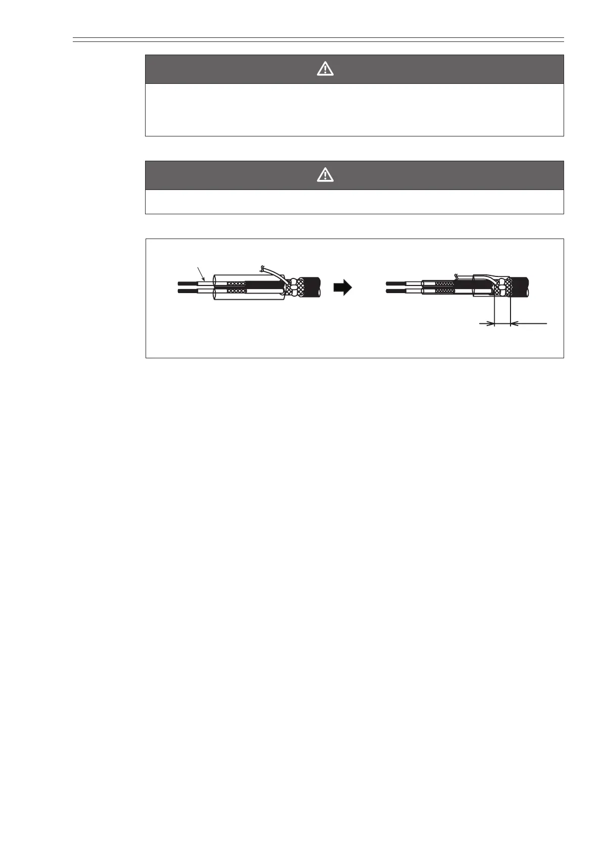
Do not cut into the conductive tube.
sheath
18 mm
A-wire
B-wire
C-wire
C-wire
Figure 2-53 Attaching the lead wires (SA and SB)
(7) Wind insulating tape around each inside shield and then around each outside
shield.
(8) Attach markers to the lead wires.
(9) Crimp the terminals onto each lead wire. Test each terminal by pulling on it to
make sure the terminal will not come o.