Installation Azbil Corporation
2-48 MagneW FLEX+/PLUS+ Electromagnetic Flowmeter Detector
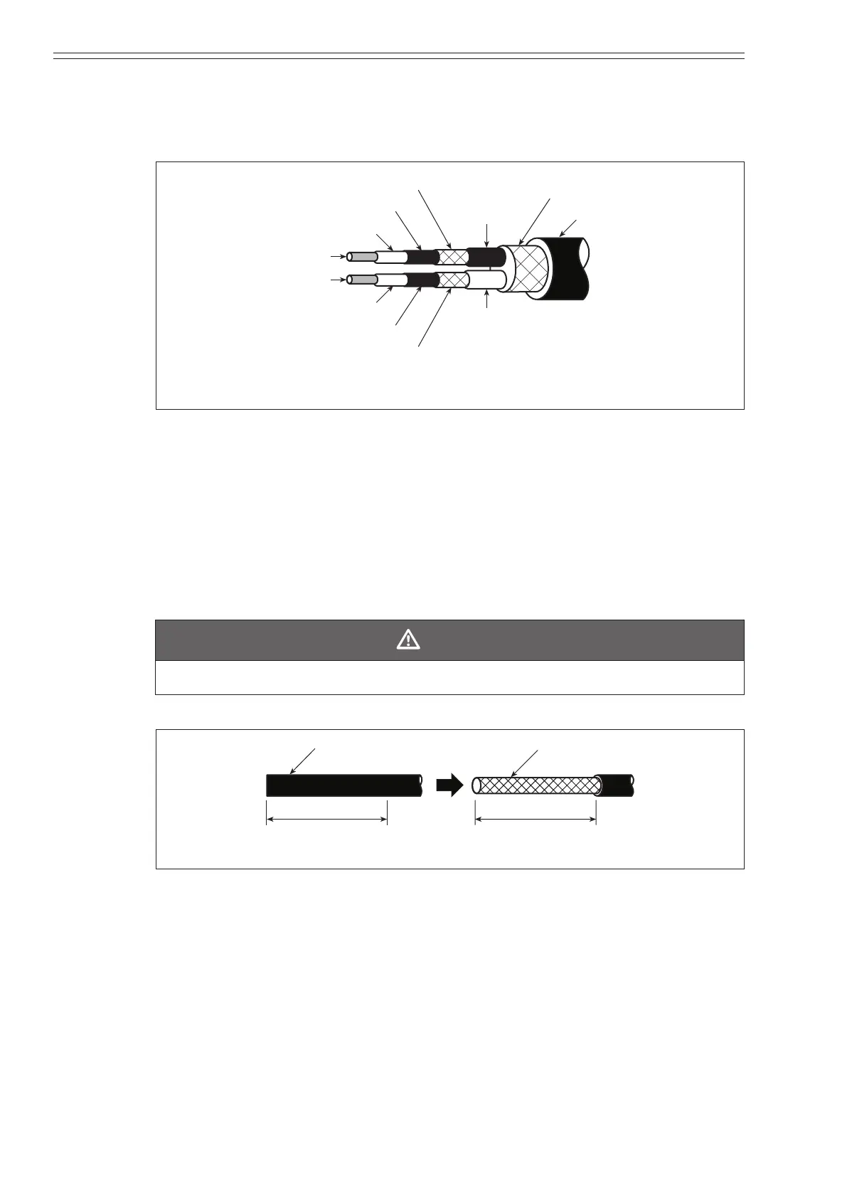
Dedicated cable structure
The structure of the dedicated cable is shown in the following gure. The cable must
be properly dressed to insure proper connection.
Insulator (white)
Conductive tube (black)
Inside sheath
(black)
Outside shield
Insulator (white)
Conductive tube (black)
Inside sheath
(white)
Conductive wire (A)
Conductive wire (B)
Figure 2-38 Dedicated cable structure
~Note
The conductive tubing (black) for conductive wires (A) and (B) is to
be removed up to the end of the inside shield.
Dressing the dedicated cable : Converter side
To dress the dedicated cable:
(1) Scribe (cut) a line in the outside sheath (black) as shown in the following gure
and remove the sheathing. The length is 75mm (2.95 inch).
CAUTION
Do not cut into the outside shield.
75 mm (2.95inch) 75 mm (2.95inch)
Outside shieldOutside sheath (black)
Figure 2-39 Trimming the outside sheath
~Note
If the terminal of the converter is designed not to use a shield drive,
remove the outside shield and skip to Step 4.
(2) Wind the lead wire once around the outside shield.
(3) Solder the lead wire (C-wire) to the middle of the 5 mm (0.2 inch) length. Make
the length of the lead wire slightly longer than necessary and trim it to the
specied length in Step 10.