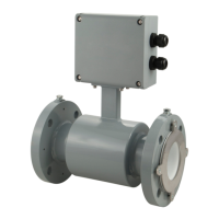
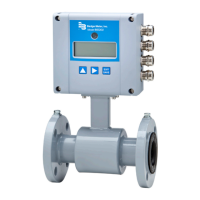
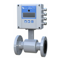
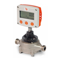
Measurements
Full Scale Flow
[Factory Set]
U
Use Full Scale Flow to set the maximum flow the system is expected to measure. This parameter has
influence on other system parameters, which include:
• Frequency Output – Full scale frequency is observed at Full Scale Flow
• Low Flow Cutoff – Changes to Full Scale Flow affect the measuring cut-off threshold of the meter
• Alarm Outputs – Changes to Full Scale Flow adjust the thresholds for generating set point alarms
• Pulse Outputs – Changes to Full Scale Flow adjust the pulse frequency and duty cycle
• Analog Outputs – Changes to Full Scale Flow adjust the interpretation of the analog output signal
Change the Full Scale Flow based on the meter size and the application requirements. Verify that the
Full Scale Flow falls within the meter suggested flow range limits. The flow velocity limits range from
0.1…39.4 feet/second. Full Scale Flow is valid for both flow directions.
OTE: N If the flow rate exceeds the full scale setting, an error message indicates that the configured
full scale range has been exceeded. However, the meter continues to measure. This affects the
latency of the pulse outputs and possibly causes overflow. Analog output may also be placed
in alarm mode.
To change the Full Scale Flow, follow these steps from the Measurements menu:
1. Select Full Scale Flow to view the Full Scale Flow display.
2. Select a value for Full Scale Flow.
3. Press [E] to save the Full Scale Flow value and return to the Measurements menu.
Low Flow Cutoff
[0.2%]
U
Low flow cutoff defines the threshold at which flow measurement is forced to zero. The cutoff value can
be set at 0…10% of the Full Scale Flow. Increasing this threshold helps prevent false readings during “no
flow” conditions possibly caused by pipe vibration or inherent system noise.
To change the Low Flow Cutoff value, follow these steps from the Measurements menu:
1. Select Low Flow Cutoff to view the Low Flow Cutoff display.
2. Select a value for low flow cutoff.
3. Press [E] to save the new low flow cutoff value and return to the Measurements menu.
Flow Direction
[Bi-Directional]
U
Use Flow Direction to set the meter to measure forward flow only (uni-directional) or both forward and
reverse flow (bidirectional).
Uni-Directional
Flow is totalized in only one direction. The flow direction is indicated by the arrow on the sensor label.
Uni-directional measurements on the main display screen include:
• T1: Registers forward flow, resettable by menu or Modbus RTU
• T2: Registers forward flow, resettable by menu, Modbus RTU or digital input configured for
Remote Reset
Bi-Directional
Flow is totalized in both directions. Bidirectional measurements on the main display screen include:
• T+: Registers forward flow, resettable by menu or Modbus RTU
• T–: Registers reverse flow, resettable by menu or Modbus RTU
• TN: Registers total flow, T+, T–, resettable by menu or Modbus RTU
To change the flow direction follow these steps from the Measurements menu.
1. Select Flow Direction to view the Flow Direction display.
2. Select Uni-Directional or Bi-Directional.
3. Press [E] to save the flow direction and return to the Measurements menu.
A change of the flow direction can be signaled by the digital outputs.
Using the Main Menu Programming Options
Page 39 March 2022 MAG-UM-01272-EN-21

 Loading...
