EasyManuals Logo

Baldor MicroFlex Installation Manual

Baldor MicroFlex
124 pages
To Next Page IconTo Next Page
To Previous Page IconTo Previous Page
Page #101 background imageLoading...
Page #101 background image
www.baldormotion.com
Accessories A-7MN1919
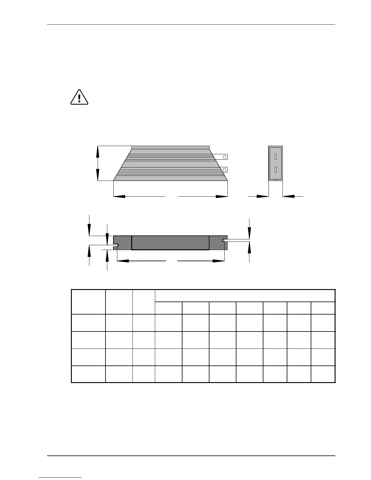
A.1.4 Regeneration resistors
Depending on the application, MicroFlex might require an external regeneration resistor to be
connected to pins R1 and R2 of connector X1. The regeneration resistor dissipates energy
during braking to prevent an over-voltage error occurring. See sections 3.6 and 3.7 for details
about choosing the correct resistor .
WARNING: Electrical shock hazard. DC bus voltages may be present at these
terminals. Use a suitable heatsink (with fan if necessary) to cool the
regeneration resistor . The regeneration resistor and heatsink (if present)
can reach temperatures in excess of 80 °C (176 °F).
A
B
C
E
D
G
F
Baldor
c
a
t
a
l
o
g
Power
W
Res.
Dimensions mm (inches)
ca
t
a
l
og
number
W
A B C D E F G
RGJ139 100 39 165
(6.49)
41
(1.61)
22
(0.87)
152
(5.98)
12
(0.47)
10
(0.39)
4.3
(0.17)
RGJ160 100 60 165
(6.49)
41
(1.61)
22
(0.87)
152
(5.98)
12
(0.47)
10
(0.39)
4.3
(0.17)
RGJ260 200 60 165
(6.49)
60
(2.36)
30
(1.18)
146
(5.75)
17
(0.67)
13
(0.51)
5.3
(0.21)
RGJ360 300 60 215
(8.46)
60
(2.36)
30
(1.18)
196
(7.72)
17
(0.67)
13
(0.51)
5.3
(0.21)
Figure 50 - Regeneration resistor dimensions

Table of Contents

Other manuals for Baldor MicroFlex

Questions and Answers:

Question and Answer IconNeed help?

Do you have a question about the Baldor MicroFlex and is the answer not in the manual?

Baldor MicroFlex Specifications

General IconGeneral
BrandBaldor
ModelMicroFlex
CategoryAmplifier
LanguageEnglish

Related product manuals