www.baldormotion.com
Feedback 4-7MN1919
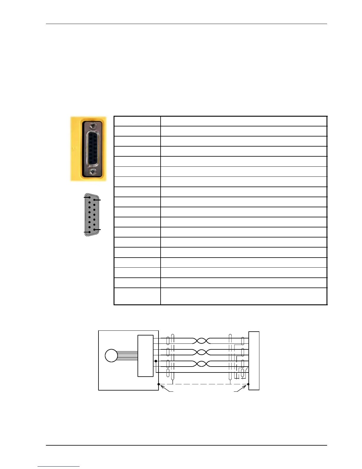
4.1.2 SSI feedback - X8
The SSI (Synchronous Serial Interface) encoder interface is specifically designed for use with
Baldor SSI motors, which incorporate a custom Baumer SSI encoder. Correct operation with
other SSI interfaces cannot be guaranteed. The SSI encoder connections are made using the
15-pin D-type female connector X8. Twisted pair cables must be used for the complementary
signal pairs e.g. Data+ and Data-. The overall cable shield (screen) must be connected to the
metallic shell of the D-type connector. Connector X8 includes a ’Sense’ pin, which is used to
detect the voltage drop on long cable runs. This allows the MicroFlex to increase the encoder
supply voltage on pin 12 to maintain a 5V supply at the encoder.
Location
Connector X8, 15-pin D-type female connector
Pin Encoder function
1 Data+
2 Clock+
3 (NC)
4 Sense
5 (NC)
6 (NC)
7 (NC)
8 (NC)
9 Data-
10 Clock-
11 (NC)
12 5-11V out
13 DGND
14 (NC)
15 (NC)
Description SSI encoder input, non-isolated. Pin 12 provides
power to the encoder (200mA max).
Data+
Data-
+5V
DGND
1
9
12
13
10
2
X8
Absolute
Encoder
Clock-
Clock+
Twisted pairs
Chassis
Connect overall shield
to connector backshells.
Connect internal
shields to pin 13.
Motor
4
Sense
SSI
Interface
Figure 17 - SSI encoder cable connections
1
8
9
15