www.baldormotion.com
Feedback 4-11MN1919
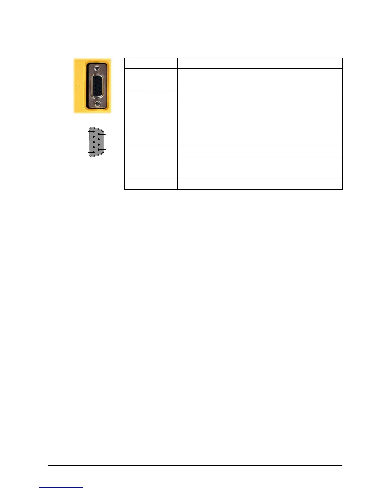
4.1.4 Encoder output - X7
Location Connector X7
Pin Name
1 CHA+
2 CHB+
3 CHZ+
4 (NC)
5 DGND
6 CHA-
7 CHB-
8 CHZ-
9 (NC)
Description Encoder output on a 9-pin female D-type connector
This output can be used for position feedback to a host positioner , or in master/slave situations
where the axis movement can be transmitted to another controller. It is recommended that this
output only drives one output circuit load. The encoder outputs are differential and conform to
the RS422 electrical specification. Shielded twisted pair cable is recommended.
If the MicroFlex is configured for incremental encoder feedback, X7 duplicates the encoder
signals entering X8. If operating in Halls-only mode, there will be no encoder output at X7.
If the MicroFlex is configured for SSI feedback, a simulated encoder output is produced at X7.
The default simulated encoder output resolution is 16384 counts per revolution, but this can be
altered using the Drive Setup Wizard in Mint W orkBench. At 62.5 microsecond intervals (a
16kHz sampling rate), the simulated encoder output generates a burst of A and B pulses (and
a Z pulse if required). The frequency and length of the burst is varied to represent the change
in the input encoder’s position during the preceding 62.5 microsecond interval. See the
keyword ENCODERLINESOUT in the Mint help file.
If the MicroFlex has resolver feedback, a simulated encoder output is produced at X7. If the
resolver input has been configured to simulate an encoder input of 1024 pulses per revolution
(ppr), the output at X7 can be set to either 512 or 1024 ppr. If the resolver input has been
configured to simulate an encoder input of 4096 ppr, output modes of 512, 1024, 2048 and
4096 ppr are possible. Note that these values represent actual encoder lines, not quadrature
counts. The simulated encoder output is in the same direction as the resolver input. See the
keyword ENCODERLINESOUT in the Mint help file.
1
5
6
9