www.baldormotion.com
4-2 Feedback MN1919
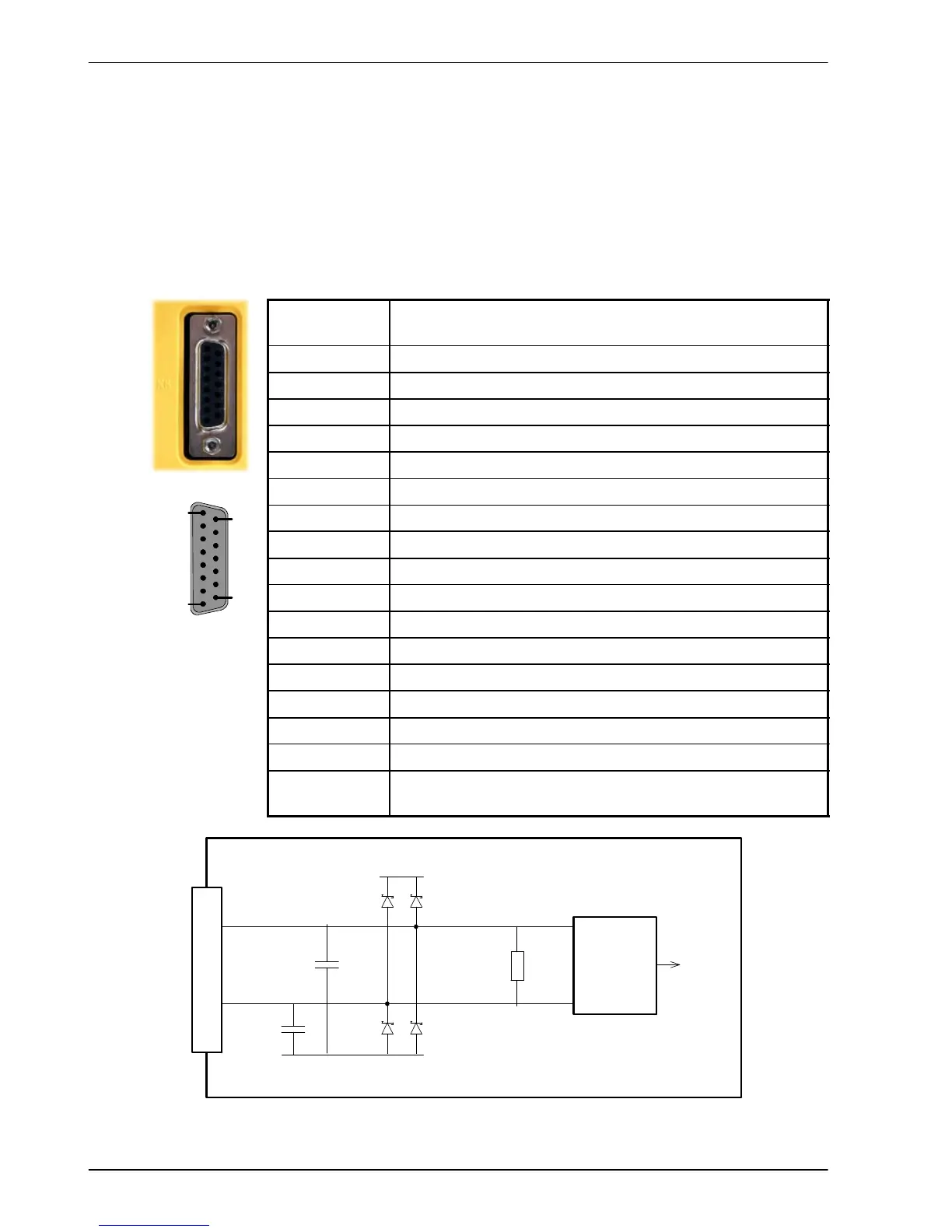
4.1.1 Encoder feedback - X8
The encoder connections (ABZ channels and Hall signals) are made using the 15-pin D-type
female connector X8. Twisted pair cables must be used for the complementary signal pairs
e.g. CHA+ and CHA-. The Hall inputs may be used as differential inputs (recommended for
improved noise immunity) or single ended inputs. When used as single ended inputs, leave the
Hall U-, Hall V- and Hall W- pins unconnected. The overall cable shield (screen) must be
connected to the metallic shell of the D-type connector. Connector X8 includes a ‘Sense’ pin,
which is used to detect the voltage drop on long cable runs. This allows the MicroFlex to
increase the encoder supply voltage on pin 12 to maintain a 5V supply at the encoder.
Location
Connector X8
15-pin D-type female connector (not high density)
Pin Encoder function
1 CHA+
2 CHB+
3 CHZ+
4 Sense
5 Hall U-
6 Hall U+
7 Hall V-
8 Hall V+
9 CHA-
10 CHB-
11 CHZ-
12 +5V out
13 DGND
14 Hall W-
15 Hall W+
Description Incremental (UVW) encoder input, non-isolated. Pin 12
provides 5-11V for encoders requiring power (200mA max)
CHA-
CHA+
MicroFlex
AM26LS32
Differential
line receiver
to CPU
120R
+5V
47pF
47pF
DGND
1
9
Figure 10 - Encoder channel input circuit - Channel A shown
1
8
9
15