www.baldormotion.com
A-2 Accessories MN1919
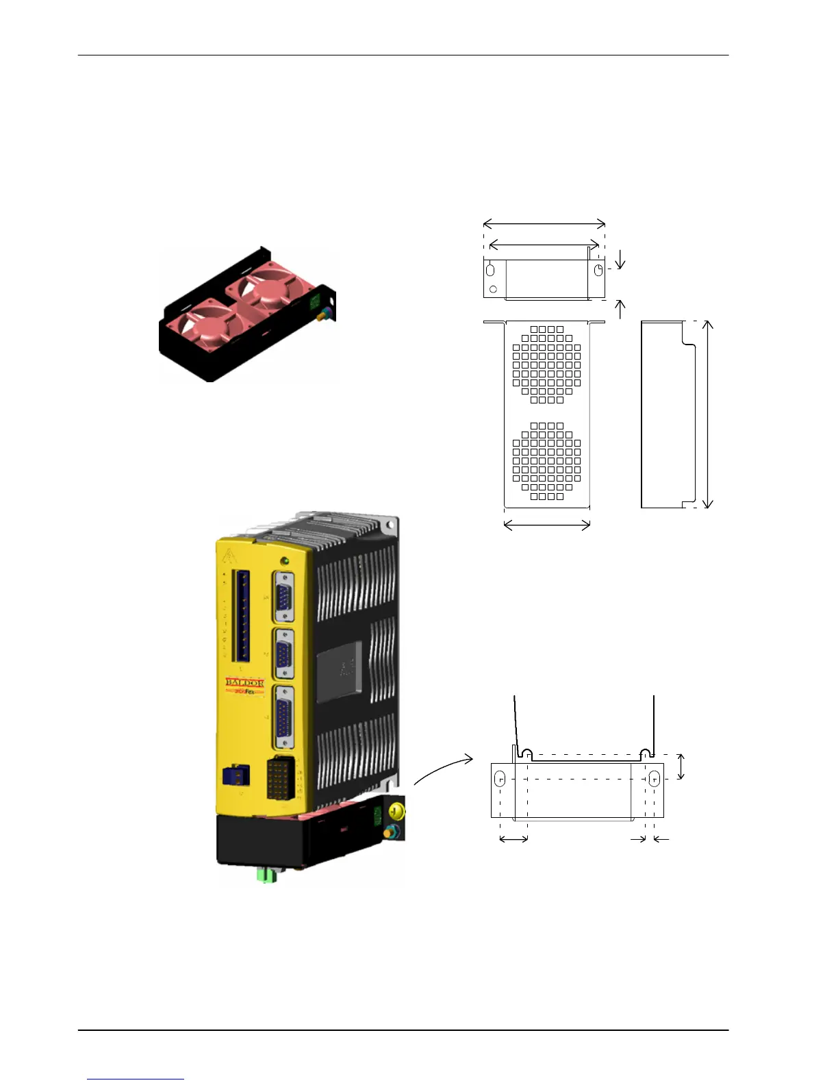
A.1.1 Fan tray
The fan tray (Baldor part FAN001-024) provides sufficient cooling for the 3A, 6A or 9A
MicroFlex. It requires 23 - 27.5VDC at 325mA, which may be sourced from the same filtered
control circuit supply used for the MicroFlex. The MicroFlex is UL listed (file NMMS.E128059)
when used in conjunction with the fan tray , mounted exactly as shown in Figure 45.
Assembled MicroFlex
and fan tray
Fan tray
FAN001-024
94 (3.7)
84 (3.3)
66 (2.6)
142.5 (5.6)
21.5
(0.85)
Fan tray
dimensions
16
(0.63)
Bottom of MicroFlex
4.5
(0.18)
17.3
(0.68)
Position of fan tray mounting
holes relative to MicroFlex
It i s important that the fan tray is mounted in
close proximity to the Mic roFlex as shown
above. Failure to do so will result in decreased
cool ing effici ency.
Fan tray
Figure 45 - Fan tray