www.baldormotion.com
3-18 Basic Installation MN1919
3.5.1 Motor circuit contactors
If required by local codes or for safety reasons, an M-Contactor (motor circuit contactor) may
be installed to provide a physical disconnection of the motor windings from the MicroFlex (see
section 3.5). Opening the M-Contactor ensures that the MicroFlex cannot drive the motor,
which may be necessary during equipment maintenance or similar operations. Under certain
circumstances, it may also be necessary to fit a brake to a rotary motor . This is important with
hanging loads where disconnecting the motor windings could result in the load falling. Contact
your local supplier for details of appropriate brakes.
CAUTION: If an M-Contactor is installed, the MicroFlex must be disabled at least
20ms before the M-Contactor is opened. If the M-Contactor is opened
while the MicroFlex is supplying voltage and current to the motor, the
MicroFlex may be damaged. Incorrect installation or failure of the
M-Contactor or its wiring may result in damage to the MicroFlex.
Ensure that shielding of the motor cable is continued on both sides of the contactor .
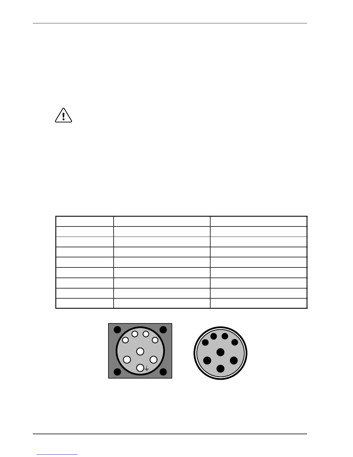
3.5.2 Motor power cable pin configuration - Baldor BSM rotary motors
Figure 8 shows the pin configuration for a typical Baldor motor cable, part number
CBL025SP-12:
Signal name
Motor / cable pin Motor cable wire color
Motor U 1 Black, labeled ‘1’
Motor V 4 Black, labeled ‘2’
Motor W 3 Black, labeled ‘3’
Earth/ground 2 Green/Yellow
Thermal switch A Green
Thermal switch B White
Brake C Blue
Brake D Red
Cable connector end view
(female)
1
B
A
3
2
4
Motor power connec tor
(male)
1
B
A
3
2
4
C
D
C
D
Note:
Not all motors
arefittedwith
a brake so
pins C and D
might not be
connec ted.
Figure 8 - Baldor motor power cable pin configuration