www.baldormotion.com
Basic Installation 3-17MN1919
3.5 Motor connections
MicroFlex will operate with a large number of brushless servo motors. For information on
selecting Baldor servo motors please see the sales brochure BR1202, available from your
local Baldor representative. The motor must be capable of being powered by an inverter PWM
output - see section 8.1.3 for details. The motor can be connected directly to the MicroFlex or
through a motor contactor (M-Contactor). The motor outputs are conditionally short-circuit
proof. Motors should ideally have a minimum inductance of 1mH per winding; for motors with
lower inductance an output reactor may be fitted in series with the motor.
When using a Baldor motor, the parameters for managing motor overloads are configured
automatically by the Commissioning Wizard (see section 6.2.3). If they need to be changed, or
you are using an alternative motor, use the Parameters tool in Mint WorkBench (see section
6.3.2).
Location
Connector X1
AC supply volt a ge 115VAC, 1Φ 230VAC, 1Φ 230VAC, 3Φ
Output volta ge range 0-115VAC, 3Φ 0-230VAC, 3Φ 0-230VAC, 3Φ
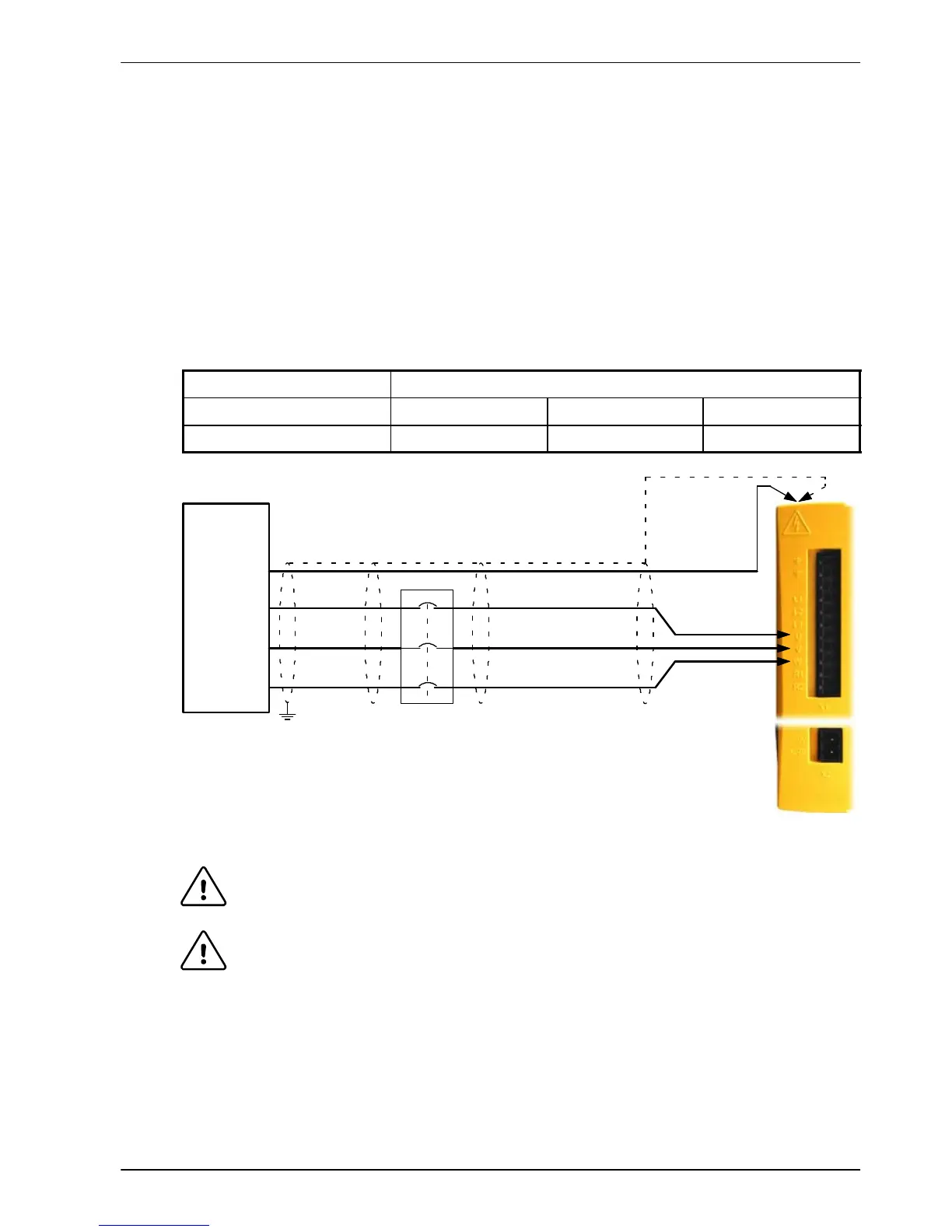
Unshielded
lengths should
be as short as
poss ible.
V
W
U
Motor
To earth/ground outer
shield, use 360°
clamp connec ted to
top of drive
Optional motor
circ uit contactors
To earth/ground
outer shi eld,
use 360° cl amp
connec ted to
back plane
Earth
Connect m otor
earth/ground
to protective
earth on top of
drive
Figure 7 - Motor connections
CAUTION: Do not connect supply power to the MicroFlex UVW outputs. The
MicroFlex might be damaged.
CAUTION: The motor leads U, V and W must be connected to their corresponding U,
V or W terminal on the motor. Misconnection will result in uncontrolled
motor movement.
The motor power cable must be shielded for CE compliance. The connector or gland used at
the motor must provide 360 degree shielding. The maximum recommended cable length is
30.5m (100ft).
Note: For CE compliance the motor earth/ground should be connected to the drive
earth/ground.