www.baldormotion.com
Input / Output 5-17MN1919
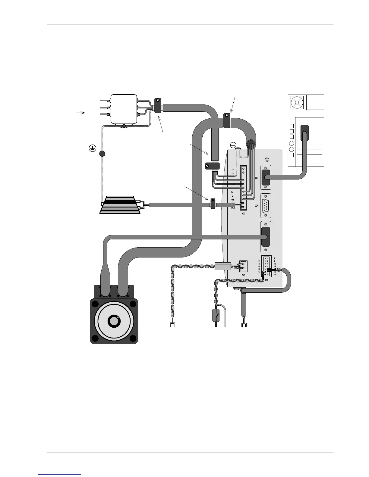
5.5 Connectio n summary - recommended system wiring
As an example, Figure 42 shows the recommended wiring necessary for the MicroFlex to
control a motor , while conforming to the EMC requirements for ‘industrial’ environments.
COM
Host PC
AC power
Motor power U V W
Serial
communication
Control circuit supply.
Use twisted pair cable
with a ferrite sleeve
(see section 3.4.8).
Motor
+24V
H The MicroFlex should be mounted on an earthed metal bac kplane.
H Ensure cables do not obstruct airflow to the heatsi nk.
H Motor represents a typical Baldor BSM motor. Linear motors may al so be controlled by MicroFlex.
H Conductive shield earth/ground clamps are not supplied.
H When using single phase supplies it may be necessary to reverse the AC power filter - see section 3.4.7.2.
0V
Filter
L1
L2
L1
L2
L3
Star
point
L1
L2
L3
L3
Connect m otor
power cable shield
to metal backplane
using conduc tive
shield clamp
Drive enable
input
+24V 0V
PE
From
fuses
AC power in
Motor feedback
Regen
Shielded twisted pair, cl amped to
metal backplane near drive using
conduc tive shield earth/ground
clamp (see sections 3.6 and C.1.7).
Connect AC power cable shield to
metal backplane using conduc tive
shield clamp (see section C.1.7).
Demand input: ±10V analog i nput
(shown) or +5V step and direction
inputs. Use shielded twisted pair(s) for
demand i nput(s). Connect c able shield
to the bottom of MicroFlex usin g
conduc tive shiel d earth/ground clamp.
Optional regen resistor
(Dynamic brake)
Figure 42 - Recommended system wiring