www.baldormotion.com
3-20 Basic Installation MN1919
3.6 Regeneration resistor (Dynamic Brake resistor)
An optional external regeneration resistor may be required to dissipate excess power from the
internal DC bus during motor deceleration. The regeneration resistor must have a resistance
of at least 39Ω, and an inductance of less than 100μH. Care should be taken to select the
correct resistor for the application - see section 3.7. Suitable regeneration resistors are listed
in section A.1.4. The regeneration resistor output is conditionally short-circuit proof.
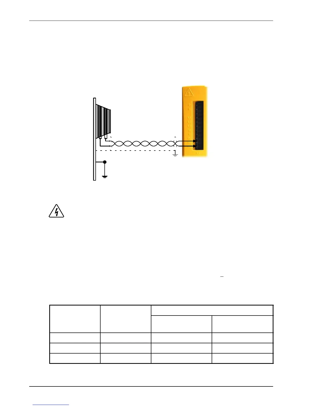
Regeneration
resistor
STAR
POINT
Earth/ground outer shield,
using 360° c onductiv e
clamp connec ted to
enclosure backplane
Figure 9 - Regene ration resistor connections
DANGER: Electrical shock hazard. DC bus voltages may be present at these
terminals. A regeneration resistor may generate enough heat to ignite
combustible materials. To avoid fire hazard, keep all combustible
materials and flammable vapors away from the resistor .
3.6.1 Regeneration capacity
The regeneration capacity of the MicroFlex can be calculated from the following formula:
where the Regen switching threshold is 388 V. This gives the following typical values:
MicroFlex
DC bus
cap acit ance (μF)
115 VAC supply 230 VAC supply
FMH2A01/3... 560 34.7 12.5
FMH2A06... 1120 69.4 25
FMH2A09... 1680 104.2 37.6
Table 5 - Regeneration capa c ity
E = 0.5 × DC bus capacitance ×
(
Regen switching threshold
)
2
−
2
× Supply voltage
2