www.baldormotion.com
Input / Output 5-5MN1919
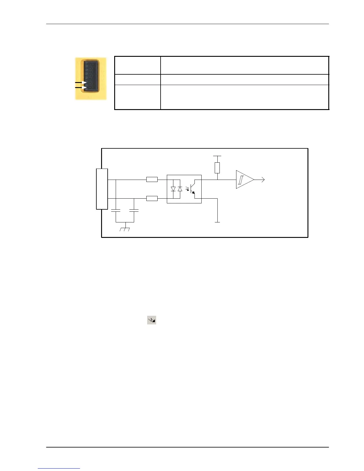
5.3.1 Drive enable input - X3
Location Connector X3, pins 6 & 7
(Mating connector: W eidmüller Minimate B2L 3.5/14)
Name Drive enable
Description Dedicated drive enable input.
Nominal input voltage: +24VDC
(input current not to exceed 50mA)
The drive enable input is buffered by a TLP280 opto-isolator, allowing the input signal to be
connected with either polarity.
Drive
Enable+
100R
TLP280
DGND
Mint
DRIVEENABLE-
SWITCH
10k
Vcc
MicroFlex
Drive
Enable-
4n7
3k3
74AHC14
4n7
7
6
Figure 28 - Drive enable input circuit
In normal use, the drive enable input controls the enabled status of the drive. However, when
the MicroFlex is connected to Mint WorkBench, additional methods are available for controlling
the drive enable status. In all cases, the drive enable input must be active and there must be
no errors present before the MicroFlex can be enabled.
H The drive enable button
on the motion toolbar toggles the enable/disable status.
Alternatively , the Mint command DRIVEENABLE.0=1 canbeusedinthecommand
window to enable the MicroFlex; DRIVEENABLE.0=0 will disable the MicroFlex.
H The Tools, Reset Controller menu item will clear errors and enable the MicroFlex.
Alternatively , the Mint command RESET.0 can be used in the command window to
perform the same action.
The state of the drive enable input is displayed in the Mint W orkBench Spy window .
Alternatively, the state of the drive enable input can be read (but not set) using the Mint
command Print DRIVEENABLESWITCH in the command window. See the Mint help file for
details.
6
7