www.baldormotion.com
Input / Output 5-9MN1919
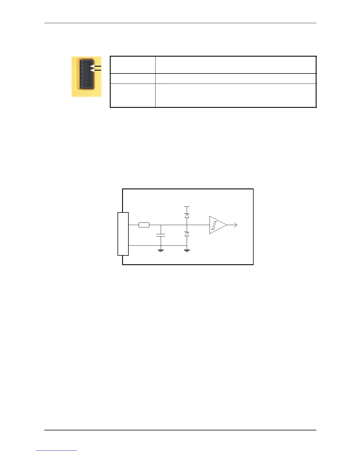
5.3.3 Step (pulse) and direction inputs - X3
Location Connector X3, pins 9 & 10
(Mating connector: W eidmüller Minimate B2L 3.5/14)
Names Step and Dir
Description Dedicated step and direction inputs.
Input voltage: +5VDC
Maximum input frequency: 1 MHz maximum
When the MicroFlex control mode is set to position control, the step and direction inputs are
used as the demand reference.
Pin 10 is the step input. The step frequency controls the speed of the motor.
Pin 9 is the direction input. The state of the direction input controls the direction of motion. If
+5V is present on pin 9, movement will be in the forward direction. If pin 9 is grounded,
movement will be in the opposite direction.
Step
DGND
MicroFlex
+5V
120R
1nF
Mint
74AHC14
10
11
Figure 32 - Step and direction input circuit - Step shown
When the MicroFlex is connected to Mint WorkBench, the following ratio can be configured
using the Operating Mode Wizard. Alternatively, the Mint keywords FOLLOWDENOM and
FOLLOWNUMERATOR can be used in the command window . See the Mint help file for details.
9
10