www.baldormotion.com
8-4 Specifications MN1919
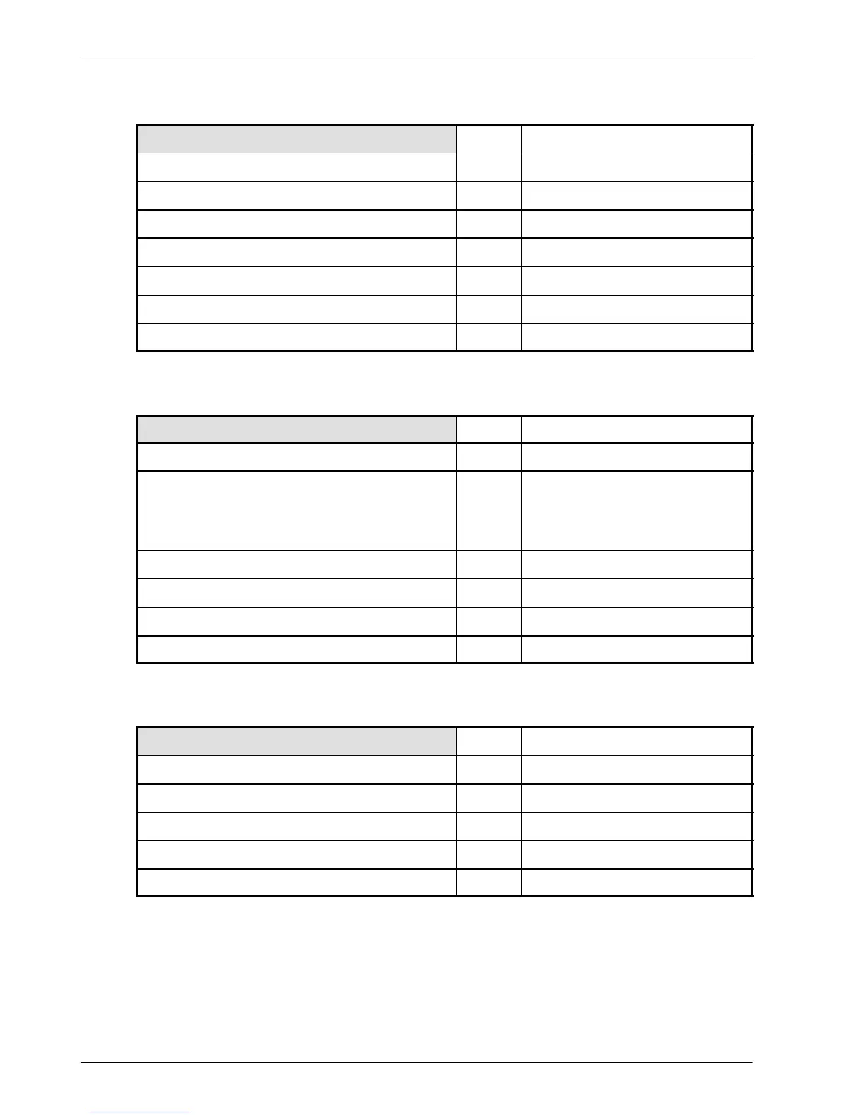
8.1.5 Analog input (X3)
Unit All models
Type Differential
Common mode volta ge range VDC ±10
Common mode rejection dB >40
Input impedance kΩ >30
Input ADC resolution bit s 12
Equivalent resolution mV ±4.9
Sampling interval μs 125
8.1.6 Digital inputs - drive enable and general purpose (X3)
Unit All models
Type Opto-isolated inputs
Input voltage
Nominal
Minimum
Maximum
VDC
24
12
30
Input current (@ Vin=24V) mA 6.7
Sampling interval ms 0.5
Maximum pulse input frequency MHz 1
Minimum pulse width μs 5
8.1.7 Step and Direction inputs (X3)
Unit All models
Type Non-isolated DC inputs
Input voltage VDC 5
Input current (maximum, per input) μA 20
Maximum step input frequency MHz 1
Minimum pulse width ns 250