Table 32: BCR Inspection Result Submodule (Ident 0x0102)
PLC Input Data Name Input Data Type
Inspection Status Word Unsigned16
Inspection Number Unsigned32
Sensor Pass/Fail Status Unsigned32
Iteration Count Unsigned32
Pass Count Unsigned32
Fail Count Unsigned32
Missed Trigger Count Unsigned32
Current Inspection Time Float 32
Inspection Status Word
Bit Position for Cyclic Input Data Function
Bit 0 System Ready
Bit 1 Inspection Pass/Fail
Bit 2 Barcode Read/No Read
Bit 3 Ready Signal Latch
Bit 4 Output 1 ON/OFF
Bit 5 Output 2 ON/OFF
Bit 6 Output 3 ON/OFF
Bit 7 Missed Trigger Occurrence
PLC Output Data Name Output Data Type
Not applicable Not applicable
Device Control Submodule
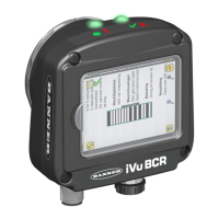
The Device Control Submodule contains controller (PLC) input and output data, including device controls for the iVu BCR.
The user-enabled Device Control Submodule is optional and plugged into Slot 1 Subslot 2 by default. The user can remove
it.
Table 33: BCR Device Control Submodule (Ident 0x0002)
PLC Input Data Name Input Data Type
Device Control ACK Word Unsigned16
Return Error Code Unsigned32
Device Control ACK Word
Bit Position for Cyclic Input Data Function
Bit 0 Product Change
Acknowledgement
Bit 1 Teach Latch Acknowledgement
Bit 2 Trigger Acknowledgement
Bit 3 Gated Trigger Acknowledgement
Bit 13 Teach Error
Bit 14 System Error
Bit 15 Command Execution Error
PLC Output Data Name Output Data Type
Device Control Command Word Unsigned16
Product Change Number Unsigned32
Device Control Command Word
Bit Position for Cyclic Output Data Function
Bit 0 Product Change Request
Bit 1 Teach Latch Request
Bit 2 Trigger Request
Bit 3 Start of Gated Trigger Request
iVu Plus BCR Gen2 Series Sensor
134 www.bannerengineering.com - Tel: + 1 888 373 6767

 Loading...
