5. Physical installation
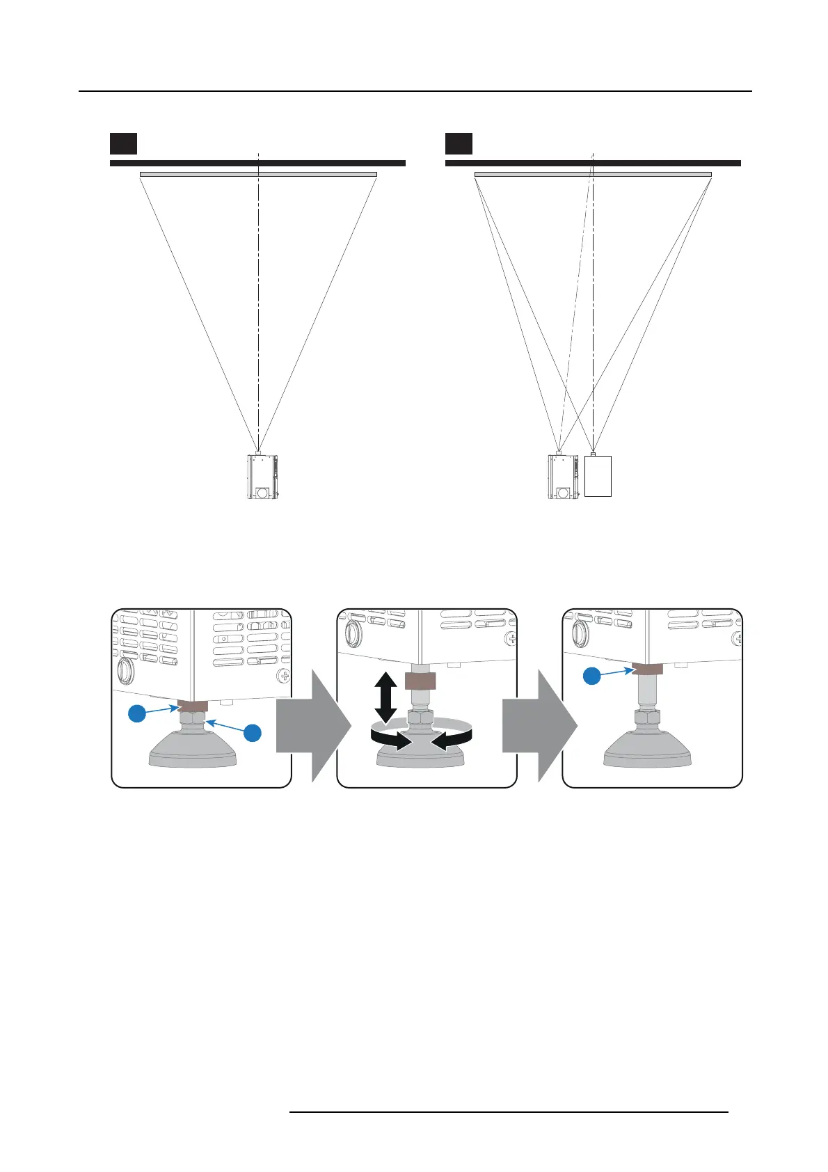
The off-center position slightly increases side keystone, but will minimize hor izontal lens offset required.
SCREEN CENTER SCREEN CENTER
OFF-CENTER
A B
Image 5-2
3. Proc eed to level the projector by adjusting the feet of the projector as follows:
- Loosen the nut (reference 1 image 5-3) on the threaded rod of the three projector feet. Use a 17 mm open wrench.
- Adjust the height of the 3 legs to level the projector. Use a 1
4 m m wrench to adjust the height as illustrated (reference 2
image 5-3).
- Secure the leg he ight by tightening the nuts (reference 1 image 5-3) of each projector foot.
1
1
2
Image 5-3
4. L ater, when the projector is up-and-running, adjust precise image geometry and placement.
Projector tilting
In an ideal installation, the DP2K -S series projector lens surface is centered with and parallel to the sc reen. This orientation helps
to ensure optimized lens performance with minimal offset. If this position is n ot possible (such as when the projector is s ignificantly
higher tha n the center of the screen ), it is better to rely on o ffset rather than extra tilt. In other words, use the S HIFT functionality
of the Lens Ho lder prior t o tilt the projec tor.
1. Before adjusting tilt, ma ke
sure the projector is as well-centered with the theatre screen as possible for the installation area.
2. C heck the degree of screen tilt, or measure this inc line with a protractor at the screen.
3. Tilt the pro jector to closely m atch this screen tilt angle as follows:
- Loosen the nut (reference 1 image 5-3) on the threaded rod of the three projector feet. Use a 17 mm open wrench.
- Adjust the height of the 3 legs un
til the projected image matches the projection port window and the screen tilt. Use a 14mm
open wrench to adjust the height as illustrated (reference 2 image 5-3).
- Secure the leg he ight by tightening the nuts (reference 1 image 5-3) of each projector foot.
R5977692 DP2K-S SERIES 10/12/2012
21

 Loading...


