601–0445 /05 Loki 81
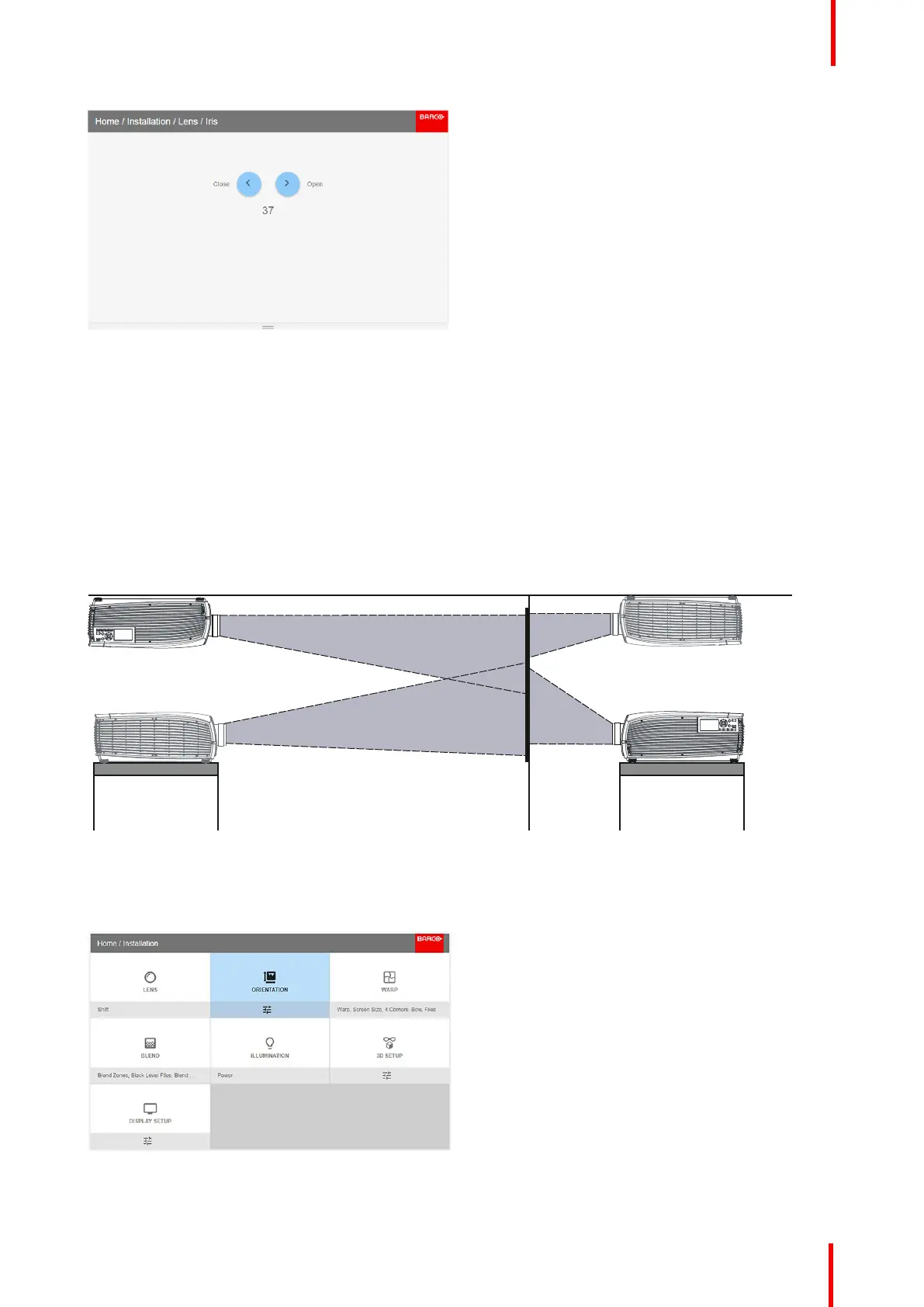
Image 8-7
Use the arrow keys to adjust Iris until preferred rendering is obtained.
8.2 Orientation
About
Installation / Orientation
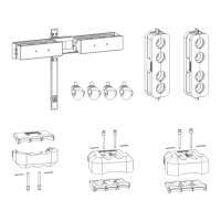
Rotate the image on the imaging device in table or ceiling and front or rear.
There are four options, as illustrated below: table / front, table / rear, ceiling / front, ceiling / rear.
Default: Table Front.
Image 8-8
How to set the correct orientation
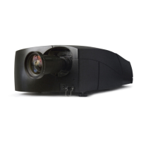
Select Orientation from the menu
Image 8-9: Orientation menu path.
The orientation menu is displayed
Installation menu