601–0445 /05 Loki82
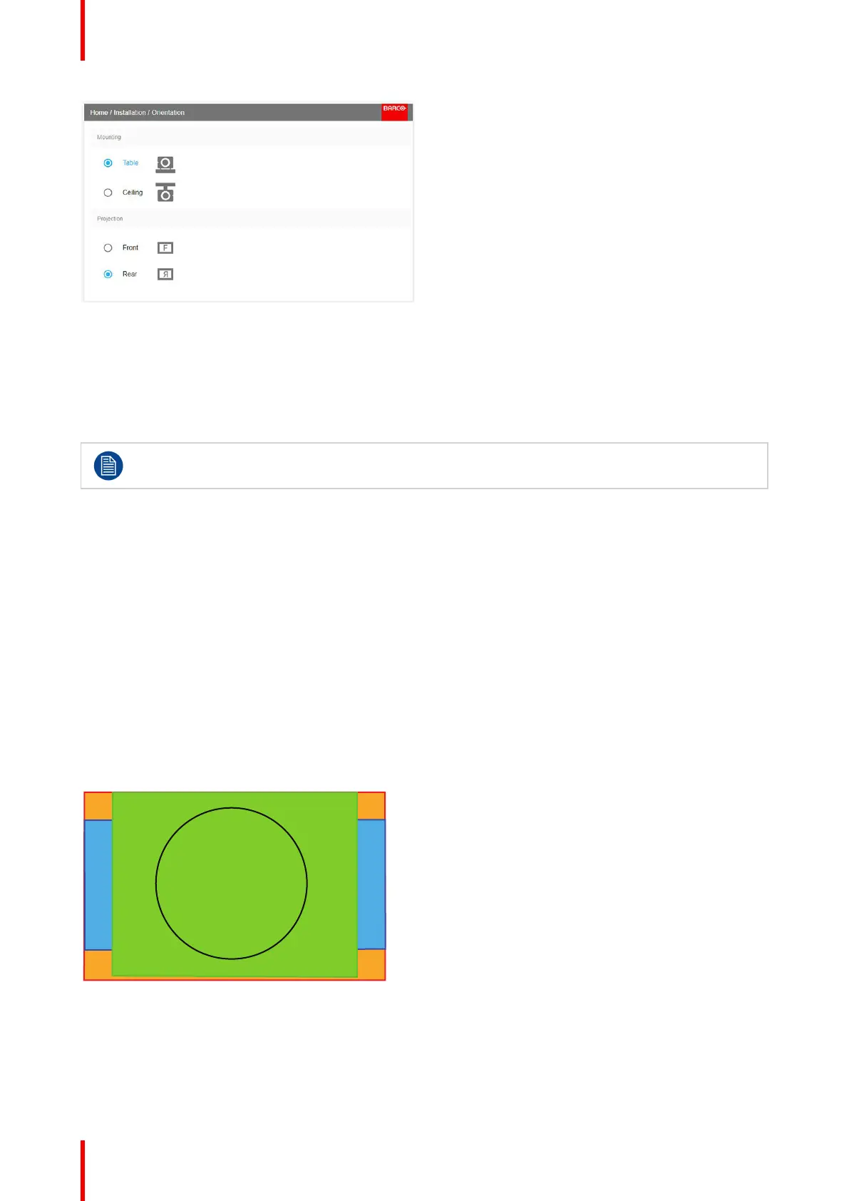
Image 8-10: Orientation Menu
Use the arrow keys to select the Mounting and Projection positions, and press OK button to activate.
8.3 Scaling modes
General
For the modes Fill Screen and Stretch, the screen size must be defined, see chapter “Warping
Screen Size”.
The purpose of the scaling mode is to adapt the image on the screen in an optimal way, based on the desired
rendering. The examples below shows a screen format of 2,35:1, and a DMD format 16:10. (WQXGA).
The scaling mode function has four different presets:
• Fill aspect
• 1:1
• Fill Screen
• Stretch.
The illustrations below shows the resolution for WQXGA, and a screen aspect ratio of 2,35:1 (Cinemascope
format. But the principle is the same also for other resolutions and screen sizes.(4K, WUXGA / 16:10, 16:9..)
Mode Fill aspect
This mode utilizes so much as possible of the native size of the DMD, and keeps the aspect ratio.
DMD Capacity: 1,6 : 1 (2560 x 1600 pixels)
Screen: 2,35 : 1 (Cinemascope)
Input signal (Source): 4 : 3
Image 8-11
1:1
This mode is an exact rendering of the source signal, pixel by pixel
Installation menu