4. Lamp & Lamp House
4
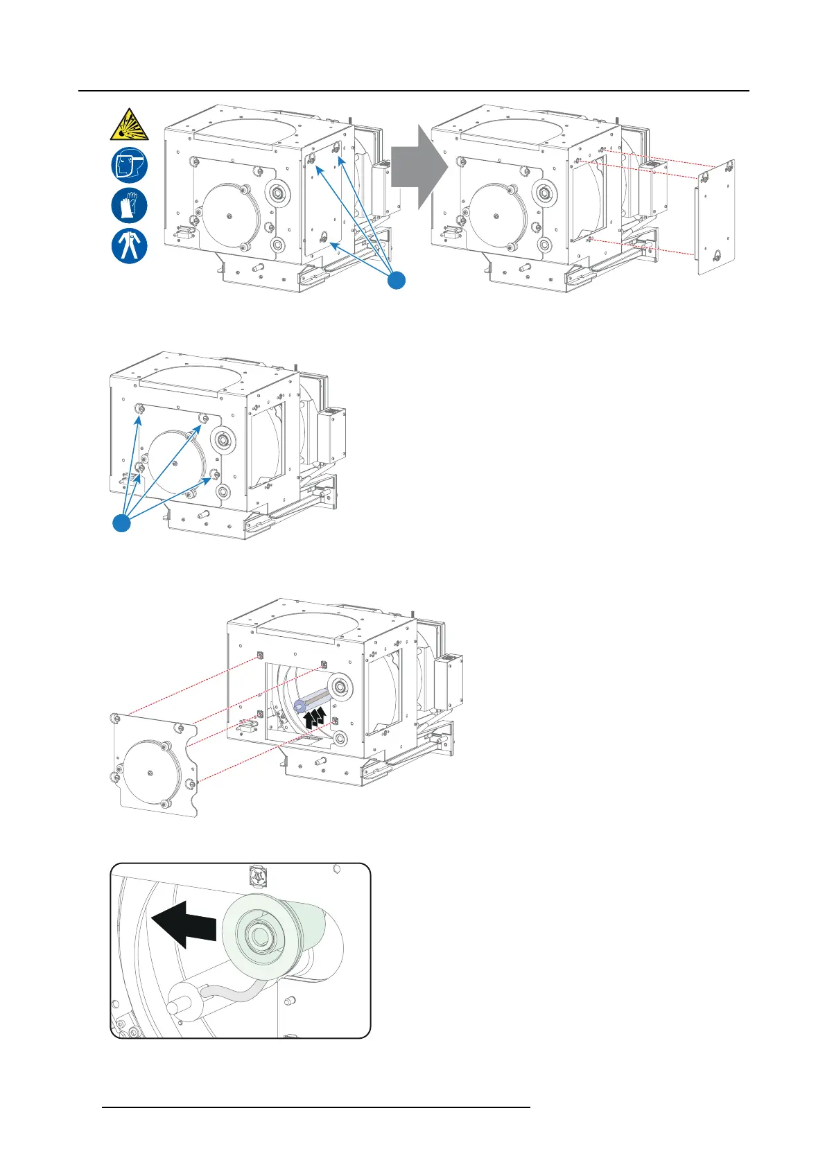
Image 4-7
3. R elease the four quarter turn screws (reference 5 imag e 4-8) of t he UV blocker assembly as illustrated. Make sure that the a node
support rem ains in its position while re leasing the screws.
5
Image 4-8
4. Support the xenon lamp inside the Lamp Ho use with one h and wh ile removing t he UV blocker as sem bly from the lamp house.
Warning: Supporting the xenon lamp with one ha nd t o prevents it from bum ping against the chassis of the Lamp House.
Image 4-9
5. Slide out the a node connector from the Lamp Hou se. The anode connector remains attached with the lamp anode wire.
Image 4-10
32 R5905067 DPXK-19B/23B/P 17/09/2012
 Loading...